Overview:
I recently went through a couple of low-beam bulbs thinking that the bulbs themselves were going bad. I did some very rudimentary analysis and determined that I had good voltage going through when the bulb was not present but the minute the bulb was inserted into the circuit, no light. I was advised by forum members that most likely root cause was a faulty relay in the CEM. I was also given some great feedback on how to troubleshoot further by KBB (see link for details:
http://www.volvoforums.org.uk/showthread.php?t=216299). I decided to simply replace the relay and see if that cured my issue...it did.
Job Difficulty:
I would rate this a level 3/10 difficulty job. Most of the steps are quite straightforward but it does require messing with the CEM AND it involves some basic soldering on a very expensive piece of electronics. Assuming all goes well you should be done this in under an hour.
Job Overview:
In short, the job involves disconnecting the battering, taking two inner trim panels off from underneath the steering wheel and removal of the CEM. Once the CEM has been removed, its a matter of locating the faulty relay, removing and replacing it with a new one of similar specs. Put it all back together and you have yourself a functioning headlight!
References:
http://www.volvoforums.org.uk/showthread.php?t=67584
http://www.volvoforums.org.uk/showthread.php?t=216299
Tools Required:
- Flashlight
- phillips screwdriver
- small flathead screwdriver
- Soldering gun, solder, solder remover tool
- 10mm socket
- patience, steady hands
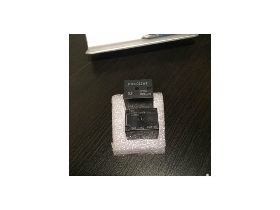
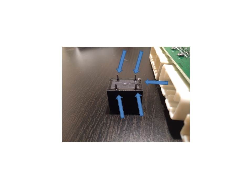
Step 1: Purchase the relay. I purchased mine from Mouser Electronics in the US (as I'm in Canada). The relay costs about $2. I bought an extra in case my other relay fails in the future. The Mouser p/n is 769-JSM1-12V-5, , the description was 15A 12VDC SPDT. It has five pins on the bottom. See the pics below for visuals of the relay.
Step 2: Disconnect the negative terminal from the battery. Also make sure that you have your radio code handy.
Step 3:Remove the felt trim which is immediately above the gas/brake pedals. It is removed by pullling on the two plastic tabs located towards the front.
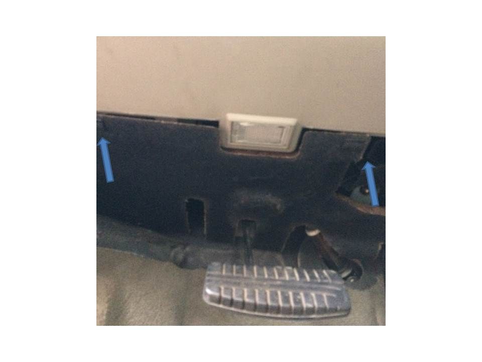
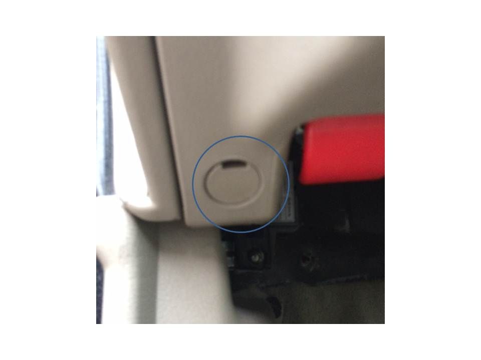
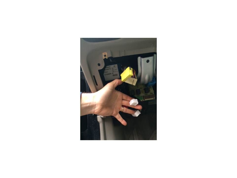
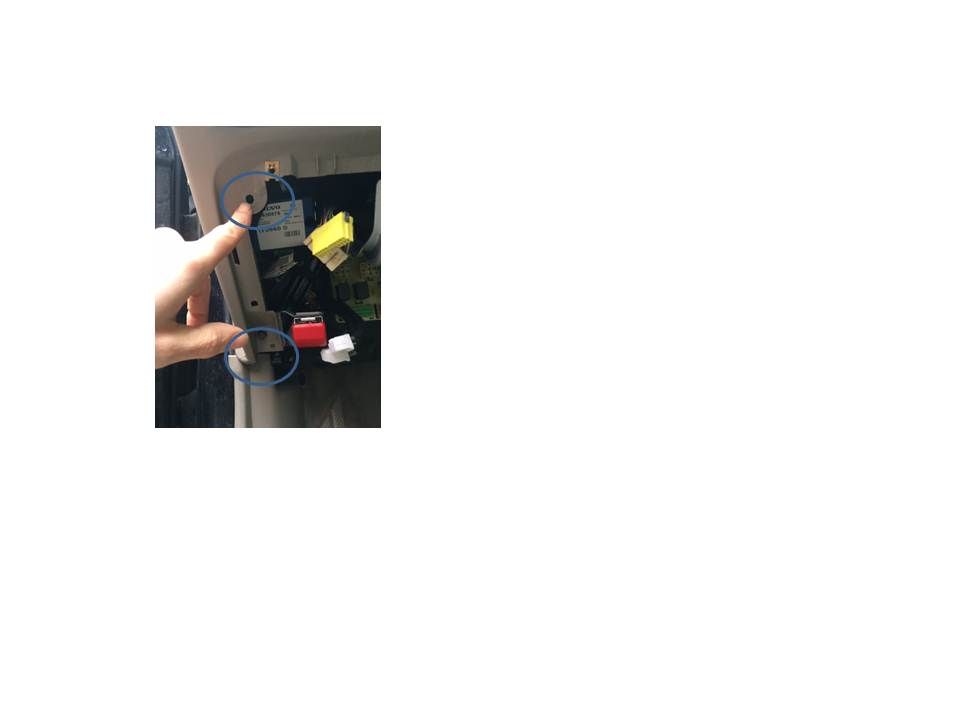
Step 4: Remove the plastic trim immediately below the steering wheel. It is removed by unscrewing 4x phillips-head screws. Note that one is located on the bottom left (next to the hood latch) and is covered by a cap. Pop off the cap to access. Note also that there is one L shaped connector on each side a the bottom. To remove the panel without breaking these pull forward (towards the seat) and then inwards. The clip can be seen in the first pic below. Lastly be careful when pulling the panel out of the footwell as the DC connection for the footwell light will need to be unplugged before you can set the panel aside.

Step 5: Unplug the four connectors to the CEM. Use a small flathead screwdriver and push the locking tab inwards to disconnect each. I was unable to get all four undone without doing step 6 first but give it a go, maybe it was just me. Make sure you at least get the bottom two white connectors out. If you don't you'll have a tough time pulling the CEM out in step 6. Also, don't do what I did and get too aggressive in pushing the locking tabs inwards. I busted one....
Step 6: Remove the CEM from vehicle. This is done by unscrewing the two phillips screws first. YOu then need to pull the CEM out sideways making sure that the metal brackets done get caught up on the trim. If you were not able to get all four connectors out, now is the time to do the rest.
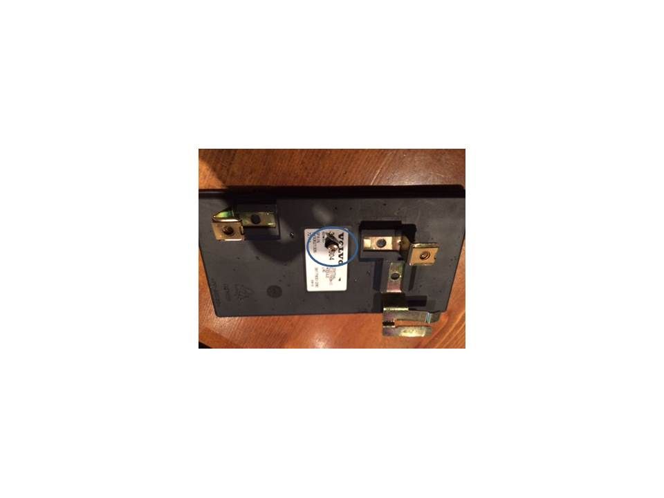
Step 7: Take the CEM appart. Don't do what I did and try to pry the two pieces apart before unscrewing the screw in the middle of the panel which for me was hidden behind the product # label. Once the screw is undone, just pry the two pieces apart carefully.
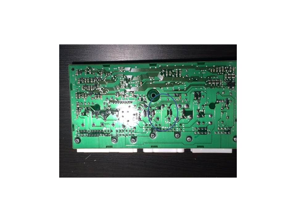
Step 8: Locate the headlamp relay. There are two. The one in the middle is for the right hand side and the other is for the left hand side.
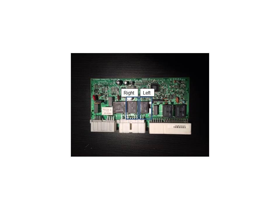
Step 9: Remove the relay. Locate the five solder points on the underside of the board and carefully remove the solder a little at a time until you can pull the relay out. I had to use a larger solder point for this vs. the one I usually use for circuit boards. It took me a good 25 minutes to get all five points clear enough that I could pull the relay out. I also cleared some of the holes up afterwards using a small drill but to make sure I could get the new one on without issue.
Step 10: Solder the new relay on. Simply push the new one in and solder it on.
Then it's simply a matter of putting everything back together in reverse.
Hope this helps someone out!