Unconfigured Ad Widget

Collapse

Announcement

Collapse
No announcement yet.

Instrument Panel Lights Failed. '92 940 2.0L

Collapse
X
 
  • Filter
  • Time
  • Show
Clear All
new posts

    #16
    The actual dimmer/rheostat module (silver box) should be the same I would think. Anyway, if you would like it, just send a PM with your address and I'll pop it in the post to you.:)

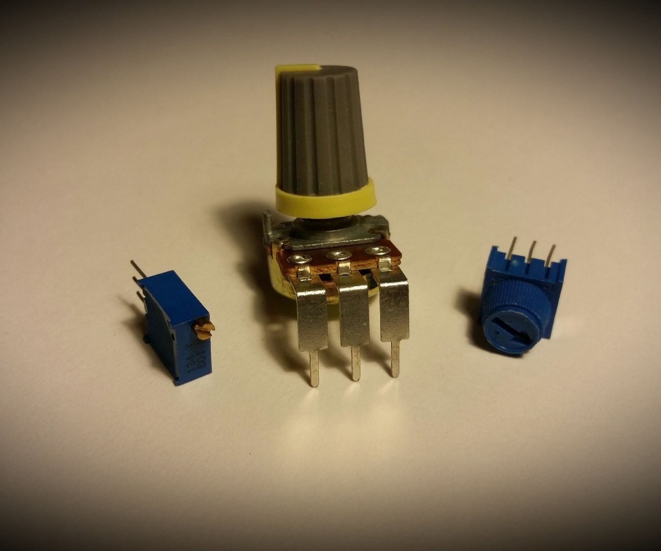
    Edit: Hmm... I've just seen this cluster in the FAQ, another style, the rheostat is obviously different:


    And yes, I know what you mean now, yours is like this:
    Attached Files
    Last edited by baggy798; Dec 11, 2012, 00:41.
    Problems with classicswede, issues with classicswede, Dai Brace engine build fail, Dai Brace can't weld..

    Comment


      #17
      To baggy798

      Yes, my dimmer switch looks like the one in your thumbnail.
      I'll try to access the back of my instrument panel at the weekend to see what my transistor looks like and get back to you after that.

      Thanks, Ian.
      Ian.

      Since 2005: 1992 Volvo 940 estate 2.0L. Manual. Daily driver and workhorse.

      Comment


        #18
        Hi Ian,

        My 1994 dash looks like the second one posted (with the large slanted connector in the bottom right of it) I would suspect that yours is the same but nothing can be confirmed until you have yours out and have a look at it.

        The other thing I would suspect is that the rheostat module is unlikely (but not impossible) to have died itself. What I would find more likely is that there is a problem with the back of the dash. These dash boards are plagued with various problems including but not limited to: dry solder joints, cracked PCB traces, oxidised and corroded screws.

        Your rheostat may be totally fine but one of the above problems suddenly appeared when you went over a bump in the road etc.

        Once you have your dash out I would suggest going over it with a fine toothed comb looking for any of the above, there are other articles on here and the maintenance FAQ with regards to what to look for. If everything checks out swap the rheostat, if it then works, swap your old one back in again to check that it wasn't just re-tightening the screws that hold it on (and more importantly form the electrical connections) that did it.

        On the flip side, it could indeed just be the rheostat (which probably has a chunky transistor at its heart but will be much more than that, Volvo will have just drawn a transistor symbol on that diagram I posted to show that it is its own discrete block of circuitry rather than a direct illustration of the component) a bulb may have blown in such a way that it caused a short and fried something further up the line in the rheostat...

        Please PM if you know of any black 940s being broken! I'm really keen for a driver's door and both front wings! Paint code 19-23

        Comment


          #19
          Thanks xad

          I don't think I'll have time this weekend now. Christmas and all that. My brother is my tame electronics expert and he is down in Wales fitting a bathroom for his daughter so he is not yet available either. Once I am able to show him the back of the instrument panel,the wiring diagrams and this thread he should be able to help out.
          I'll update the thread when I know more.
          Ian.

          Since 2005: 1992 Volvo 940 estate 2.0L. Manual. Daily driver and workhorse.

          Comment


            #20
            I've just come across this thread and I have what looks to be the same issue as @Ian21401 . What was the eventual resolution?

            I'd love to see @James_EG_940 's circuit diagram but the forum seems to have expired the attachments, presumably to save space on the server. Any chance you could re-post it?

            I haven't taken out my dashboard cluster yet but jumpering across blue and black restores power to the instrument lamps.

            Comment


              #21
              Apologies trebor for not doing a final update.
              There isn’t actually a final update as the cause was never definitively identified.
              I left the jumper between pin 4 (light blue wire) and pin 6 (black wire) as this restored all the panel illumination at max. brightness. The dimmer slider did not then work but this was not a problem as I normally have them on max. The clock adjust forward button still didn’t work either. I learned to live with it and almost forgot about it.
              In October ‘14 my speedometer stopped working but the odometer and trip meter were still working. My instrument panel/cluster is same as the image in post 16 by baggy798. After research on this forum I replaced the capacitors in the speedometer. When the instrument panel was refitted, somehow the clock adjust buttons were now working correctly but the dimmer slider still did not work so I left the jumper between 4 and 6 in place. The speedometer still had an intermittent fault so I acquired an identical instrument panel from a member of this forum and fitted that as it was received without any modification. I cannot remember, and my notes do not record it, but I must have removed the jumper from the panel light dimmer switch as my notes indicate that the panel lights, dimmer and clock adjust buttons now all worked correctly. This would seem to indicate that the cause of the original panel light, dimmer and clock adjust buttons problem was somewhere on the instrument panel.
              In April’15 whilst investigating an ABS problem the replacement speedo. developed an intermittent fault. Following more research and advice I turned my attention back to my original speedo. Following that advice I cleaned the PCB underneath the screws by removing each screw in turn and cleaning with an abrasive fibre glass pencil then lubricating with “Contralube”. (Do not use abrasive paper or wire wool as loose particles may cause a short circuit on the PCB.) I refitted this original speedo. and instrument panel.
              It has worked satisfactorily up to now and the panel lights, dimmer and clock adjust buttons continue to work satisfactorily.
              I can only assume that the original problem with the panel lights etc. was caused by some fault within the PCB of the instrument panel and cleaning the contact areas has cured it.
              All I can suggest is cleaning those PCB contact ares as I did. I wouldn’t bother with the speedo capacitors at this time unless you also have a speedo drop out problem.
              Last edited by Ian21401; Dec 17, 2019, 22:21. Reason: Add text.
              Ian.

              Since 2005: 1992 Volvo 940 estate 2.0L. Manual. Daily driver and workhorse.

              Comment


                #22
                Thanks for the write-up. I too have left the jumper in as a temporary fix. I've also got an intermitent speedo dropping-out problem so looks like I'll be taking the whole instrument panel out at some point and giving it a good going-over.

                Comment


                  #23
                  Originally posted by trebor View Post
                  Thanks for the write-up. I too have left the jumper in as a temporary fix. I've also got an intermitent speedo dropping-out problem so looks like I'll be taking the whole instrument panel out at some point and giving it a good going-over.
                  It's well worth doing the cleaning as Ian describes and also the edgees of the PCB where the multiplugs connect to the instrument cluster. Also clean the connectors on the multiplugs and use a small thin tool (screwdriver or similar) to "restretch" the connectors in the plugs to a bow shape as they become flattened with age and lose their tension.

                  Just this alone can cure a lot of the simpler maladies the instrument clusters suffer from. :thumbs_up:
                  Cheers
                  Dave

                  Next Door to Top-Gun with a Honda Elysion & S Type Jag :D Volvo gone but not forgotten........oh yeah and a CR-V for sale!

                  Comment


                    #24
                    Originally posted by trebor View Post
                    Thanks for the write-up. I too have left the jumper in as a temporary fix. I've also got an intermitent speedo dropping-out problem so looks like I'll be taking the whole instrument panel out at some point and giving it a good going-over.
                    I don’t know the year of your car.
                    Is it just the speedo. and are the odometers still working normally?
                    I’ve read elsewhere that around 1992 (give or take a year) the capacitors fitted to the Yazaki speedos. were poor quality and subject to leakage and damaging the PCB where they were located. That’s why I replaced mine. That may be the cause of your speedo. problem.
                    I’ll try to link my old speedo. post to this one as soon as I have time.
                    Ian.

                    Since 2005: 1992 Volvo 940 estate 2.0L. Manual. Daily driver and workhorse.

                    Comment


                      #25
                      Hi,

                      I finally got a chance to take the instrument panel out today - but stupidly, I hadn't seen Ian's and Laird's most recent posts so I missed the point about cleaning and re-springing the edge connectors, which could be one of my issues (see below).

                      The PCB shows signs of previous repair: two different types of screw-heads were observed, and some excess flux from, presumably, resoldering efforts. I re-tightened all the conductive screws and cleaned various connection points (but I neglected to apply any lubricant).

                      I noticed that the resistors indicated on the PCB above lamp 14 measured open circuit. I didn't want to take the PCB off the rest of the instrument cluster to look further though.

                      The instrument brightness slider measured from 273 - 1.2k ohms from black to brown/green and 1.2k - 345 ohms from brown/green to white. I don't understand what the presence of the blue cable into the brightness adjuster module is for.

                      After doing all this, one area of illumination that was previously off lit up again; but an area that was previously lit has now gone dark! This is still with the jumper in place: there's no illumination at all without it. The speedo has been working during brief trips but it's too early to call.

                      At least by doing this I've learnt how to get the unit in and out of the car!

                      I might have another go next week, but other than that.... Has anyone got any recommendations for someone who will take in one of these instrument clusters for service/repair and return it in an at least approximately good-as-new condition?

                      Comment


                        #26
                        Originally posted by trebor View Post
                        Hi,

                        I finally got a chance to take the instrument panel out today - but stupidly, I hadn't seen Ian's and Laird's most recent posts so I missed the point about cleaning and re-springing the edge connectors, which could be one of my issues (see below).

                        The PCB shows signs of previous repair: two different types of screw-heads were observed, and some excess flux from, presumably, resoldering efforts. I re-tightened all the conductive screws and cleaned various connection points (but I neglected to apply any lubricant).

                        I noticed that the resistors indicated on the PCB above lamp 14 measured open circuit. I didn't want to take the PCB off the rest of the instrument cluster to look further though.

                        The instrument brightness slider measured from 273 - 1.2k ohms from black to brown/green and 1.2k - 345 ohms from brown/green to white. I don't understand what the presence of the blue cable into the brightness adjuster module is for.

                        After doing all this, one area of illumination that was previously off lit up again; but an area that was previously lit has now gone dark! This is still with the jumper in place: there's no illumination at all without it. The speedo has been working during brief trips but it's too early to call.

                        At least by doing this I've learnt how to get the unit in and out of the car!

                        I might have another go next week, but other than that.... Has anyone got any recommendations for someone who will take in one of these instrument clusters for service/repair and return it in an at least approximately good-as-new condition?
                        If you go into your User Control Panel, click Edit Options and scroll down to Default Thread Subscription Mode, use the drop-down box to select "Instant email notification" when you post a new subject or reply to a thread, it will automatically subscribe you to that thread and when replies are recieved, you will get an email notification.

                        That way you will know there are replies to the thread/subject.

                        Back to the subject of the thread, i'd strongly suggest you do like Ian and i have advised, also i doubt those are resistors, i think they're probably diodes that only conduct one way - photos would help to clarify this.

                        Have a look at this, it explains the purpose of the third blue wire on the brightness slider :

                        How to Use a Potentiometer As a Voltage Divider.: Hello and Welcome This Instructable is going to be short and sweet. I would like to share with you the power of potentiometers. A simple component that can be used as a voltage divider. You may be saying to yourself, "Duh, everyone knows that!" Well…


                        The big problem with anyone testing and repairing one of these clusters is you need to find someone who can not only repair it but test it as well. You already have the very best test-bed available - you drive it!
                        Cheers
                        Dave

                        Next Door to Top-Gun with a Honda Elysion & S Type Jag :D Volvo gone but not forgotten........oh yeah and a CR-V for sale!

                        Comment


                          #27
                          Originally posted by Laird Scooby View Post
                          If you go into your User Control Panel, click Edit Options and scroll down to Default Thread Subscription Mode, use the drop-down box to select "Instant email notification" when you post a new subject or reply to a thread, it will automatically subscribe you to that thread and when replies are recieved, you will get an email notification.

                          That way you will know there are replies to the thread/subject.

                          Back to the subject of the thread, i'd strongly suggest you do like Ian and i have advised, also i doubt those are resistors, i think they're probably diodes that only conduct one way - photos would help to clarify this.

                          Have a look at this, it explains the purpose of the third blue wire on the brightness slider :

                          How to Use a Potentiometer As a Voltage Divider.: Hello and Welcome This Instructable is going to be short and sweet. I would like to share with you the power of potentiometers. A simple component that can be used as a voltage divider. You may be saying to yourself, "Duh, everyone knows that!" Well…
                          Thanks for the tip, I hadn't realised email notifications weren't automatic.

                          I looked at the article but I'm still at a loss to understand why there are 4 wires connecting to the brightness adjuster. The diagram (Step 3) shows supply voltage coming in at the top (black wire), ground coming out of the bottom (white wire), and the output going out to the right (brown/green). So I'm afraid I still don't understand the mystery blue wire :/

                          The car's been in regular use over Christmas/New Year and I'm about to go away so won't have another opportunity to work on the dashboard for a while now :-(
                          Last edited by trebor; Jan 1, 2020, 21:42.

                          Comment


                            #28
                            Originally posted by trebor View Post
                            Thanks for the tip, I hadn't realised email notifications weren't automatic.

                            I looked at the article but I'm still at a loss to understand why there are 4 wires connecting to the brightness adjuster. The diagram (Step 3) shows supply voltage coming in at the top (white wire), ground coming out of the bottom (black wire), and the output going out to the right (brown/green). So I'm afraid I still don't understand the mystery blue wire :/

                            The car's been in regular use over Christmas/New Year and I'm about to go away so won't have another opportunity to work on the dashboard for a while now :-(
                            Any chance you can get a photo of this blue wire? I'm wondering if it's been added by a previous owner to maybe link out a bad connection or to feed an extra instrument or something.
                            Cheers
                            Dave

                            Next Door to Top-Gun with a Honda Elysion & S Type Jag :D Volvo gone but not forgotten........oh yeah and a CR-V for sale!

                            Comment


                              #29
                              Originally posted by Laird Scooby View Post
                              Any chance you can get a photo of this blue wire? I'm wondering if it's been added by a previous owner to maybe link out a bad connection or to feed an extra instrument or something.
                              I'll try and get a pic but it looks to definitely be factory fitted: it's got exactly the same crimp connector on the end of the blue wire as the other colours, there are 6 positions on the back of the adjuster module, the four coloured wires as mentioned and the remaining 2 which are blanked (I think for the digital clock adjust option, whereas my 940 has the rotary clock set knob which comes through the glass on the instrument panel itself). So it's clear that the adjuster is designed to have 4 inputs.

                              From what Ian said, it seems the brown/green output from the adjuster doesn't feed the lights directly - it goes into a small PCB on the back of the instrument panel which generates the actual current that feeds the lamps. For some reason which I don't understand, this is also fed back to the adjuster on the blue wire, which is why the link from blue to black provides 12V directly to the lamps, effectively bypassing the brightness adjustment circuit altogether. Have I got this right?
                              Last edited by trebor; Jan 1, 2020, 21:43.

                              Comment


                                #30
                                Originally posted by trebor View Post
                                I'll try and get a pic but it looks to definitely be factory fitted: it's got exactly the same crimp connector on the end of the blue wire as the other colours, there are 6 positions on the back of the adjuster module, the four coloured wires as mentioned and the remaining 2 which are blanked (I think for the digital clock adjust option, whereas my 940 has the rotary clock set knob which comes through the glass on the instrument panel itself). So it's clear that the adjuster is designed to have 4 inputs.

                                From what Ian said, it seems the brown/green output from the adjuster doesn't feed the lights directly - it goes into a small PCB on the back of the instrument panel which generates the actual current that feeds the lamps. For some reason which I don't understand, this is also fed back to the adjuster on the blue wire, which is why the link from blue to black provides 12V directly to the lamps, effectively bypassing the brightness adjustment circuit altogether. Have I got this right?
                                The blue is the earth for the dimmer illumination. Have a look at pg 38 (by document viewer number) of this pdf :


                                In other words, the blue has nothing to do with your problem so you can ignore it.

                                However, if i've understood you correctly, if you take theblack wire directly to earth, the instrument lights work?
                                Cheers
                                Dave

                                Next Door to Top-Gun with a Honda Elysion & S Type Jag :D Volvo gone but not forgotten........oh yeah and a CR-V for sale!

                                Comment

                                Working...
                                X