
|
|||||||
| PV, 120 (Amazon), 1800 General Forum for the Volvo PV, 120 and 1800 cars |
 Information
|
|
Distributor Adjustment KnobViews : 1716 Replies : 7Users Viewing This Thread : |
 |
|
|
Thread Tools | Display Modes |
 Apr 23rd, 2017, 10:09
|
#1 |
|
Member
Last Online: Yesterday 17:23
Join Date: Jan 2006
Location: Worcester
|
I need a little more advance on the timing, so I went to rotate the distributor (clockwise) to do this and found that the small "knob" on the side of the distributor is hard up against the engine block and so will not allow any further rotation.
I've often looked at this knob and though "I wonder what this does?", so I thought I'd ask the experts. My choices seem to be to "relocate" the distributor so that it no longer hits the block or to remove this small adjustment knob. Can anyone help with what this does? I've posted a photo to try to illustrate the knob. This is not a photo of my distributor. It seemed easier to use this photo than to photograph the distributor in place in a less than well lit location. I know that the number does not relate to a "standard" Volvo distributor number! |

|

|
|
Apr 23rd, 2017, 10:20
|
#2 |
|
Master Member
Last Online: Jan 24th, 2022 17:08
Join Date: Nov 2008
Location: small village in the north of Germany
|
Oiler is called this knob
turn the cap a little bit, at oil, turn back. Should be used regulary ;-) Don't remowe it-use it regards, Kay |
|
|
|
| The Following 2 Users Say Thank You to mocambique-amazone For This Useful Post: |
|
Apr 23rd, 2017, 15:03
|
#3 |
|
Premier Member

Last Online: Yesterday 23:59
Join Date: Jul 2007
Location: Connecticut, USA
|
edworcs;
Kay has answered the question, what it does...to augment, there are many places where a Distributor is supposed to be lubricated (4, 5 and 8 are the really important ones which should be touched up at every Ignition tune-up):  Source: http://www.sw-em.com/dist_lurication.jpg Further...while I understand the Distributor shown is not yours, it is clear that this Dist has Vacuum Diaphram, I expect yours does not, because if it did, VD would surely hit hit the engine block before Oiler Cup(8), preventing further adjustment. Please confirm this...and after confirming, you may use the following procedure to address your issue, the Root Cause of which is Either: Engagement of Distributor Drive Gear with Cam has been changed from standard and nominal position , as shown following, to something else (this is not a problem per se, as proven by the fact that engine runs normally, other than this minor issue it causes.) 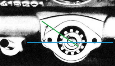 OR, Ignition Wire location has been changed by one or more stations, resulting in this abnormal position of Dist Housing. Explanation: Since I am not aware of the level of your abilities and experience, and since you are asking, and not familiar with this and how to sort it, I have to assume a non-expert level (NO insult intended here!), I will keep my explanation and recommendations as basic and highly detailed as possible and geared to an inexperience mechanic. (Unfortunately, this will make it more long and wordy, but that is the best way to help you to understand the steps, thereby assuring success!) While there are multiple ways to sort this, I have written the following procedure, and with the greatest care(!) to be the simplest: 1. With Battery disconnected, and Ignition OFF, use Fanbelt or wrench at Crankbolt Pulley, to rotate Crankshaft (in the normal direction of rotation) to a desired starting Timing point on Cyl 1 (16 Deg is good). Since Timing marks come around twice per single Dist rotation, remove Dist Cap when you believe you are at 16 Deg BTDC No1, and confirm Rotor is pointing toward station on Cap which has Ign Wire to Cyl 1. [You must confirm Rotor is pointing to Cyl 1 before proceeding...if Rotor points 180 Deg away (to Cyl 4), continue rotating Crankshaft until Timing Marks come around the next time.] 2. Note Clock position of Cyl 1 Ign Wire on Dist Cap, and note that Rotor in Dist Housing is also pointing to this Cyl 1 direction. 3. Loosen Timing locking Nut on Dist Mount Clamp at base of Dist to allow turning Dist Housing. 4. (Everything up to now has been explanation and preliminary, but: Here's is the Beef!) Rotate Dist Housing approximately 90 Deg Counter-ClockWise (or as you might say in England: Anti-Clockwise). This will rotate the Housing and Oiler (or VD if present) which is fouling on the engine block, away and clear. 5. At Dist Cap relocate all four Ignition wires, one station (90 Deg) ClockWise. Starting with Ign Wire for Cyl 1, and one at a time (think musical chairs... four wires, four stations, ClockWise!) Reference info: Rotor rotation is CCW and Firing order is 1,3,4,2. 6. When all wires are back on Dist Cap one station CW from their previous location, replace Cap on Dist Housing and lock into place using 2 Latch Clips. Verify correct Firing order of Ign Wires running to Spark Plugs. 7. Reconnect Battery, Turn Ign ON at Ign Key, and perform Static Timing (Remove Ign wire 1 from Spark Plug, lay on Valve Cover to allow seeing Spark when it occurs, then turning Dist Housing to simulate Rotor Shaft turning (CCW)...first, a few degrees CCW, the slowly CW until an Ign Spark occurs. Repeat this back and forth action a number of times or as many times as necessary, until you get a feeling for the angle at which spark occurs, then STOP turning precisely after spark occurs, rotating no further. Stating Timing is now complete! 8. Reconnect Ign Wire to Spark Plug 1. After assuring engine is clear to run. Start engine. Timing should now be fairly close to 16 Deg BTDC, which may be verified with a timing Strobe. If you checked Timing before with Strobe before and know what it was, you can adjust it in the normal manner (by turning Dist Housing and observing change at Timing marks with Strobe) to what you might want it to be (that was the original issue!), now that Dist Housing is clear and not fouling with engine block.. 9. When Timing fine adjustments are complete, tighten Timing locking Nut on Dist Mount Clamp at base of Dist. Wishing you success. Please post any questions if uncertain. Good Hunting! [Note to experienced Volvo mechanics: I invite peer review on this procedure to assure I have not missed anything. I have not written procedure to return Dist Drive Gear to its normal nominal position, preferring to keep this inexperienced mechanic's actions on topside of Dist and somewhat simpler and less intimidating.] Last edited by Ron Kwas; Apr 23rd, 2017 at 18:03. Reason: Edit 1: grammar correction Edit 2: Ring around the Rosie direction correction. Tnx to gw! |
|
|
|
| The Following User Says Thank You to Ron Kwas For This Useful Post: |
|
Apr 23rd, 2017, 17:38
|
#4 |
|
Member
Last Online: Aug 8th, 2023 18:40
Join Date: Oct 2015
Location: Inverness
|
Nice one Ron.
But if you are turning the distributor housing anti clockwise (as we say here in Scotland too!) should you not be moving the ignition wires clockwise on the distributor cap? |
|
|
|
| The Following User Says Thank You to grahamwatson For This Useful Post: |
|
Apr 23rd, 2017, 17:54
|
#5 |
|
Premier Member
Last Online: Yesterday 23:59
Join Date: Jul 2007
Location: Connecticut, USA
|
GW;
You are absolutely correct sir! I got preoccupied with the CCW vs Anti-Clockwise I guess...I will correct the procedure immediately...thanks so much for the peer review and catching this! Cheers |
|
|
|
|
Apr 23rd, 2017, 18:36
|
#6 |
|
Member
Last Online: Aug 8th, 2023 18:40
Join Date: Oct 2015
Location: Inverness
|
I assumed that was a deliberate error just to check that we were paying proper attention!
I'm getting bold now but I wonder if it is worth adding that if the 90 degree turn does not give the desired result (e.g. there is still something fouling on the engine block, or the oiler is not as convenient as we now know that it should be) there is nothing to stop you following the procedure again and turning it another 90 degrees (or even yet another 90 degrees). I find it most convenient if the cap clips are on either side of the distributor, looking at the engine from the side, but that is not always possible with all the other stuff which hangs off some distributors. |
|
|
|
|
Apr 29th, 2017, 16:53
|
#7 |
|
Member
Last Online: Yesterday 17:23
Join Date: Jan 2006
Location: Worcester
|
Ron, many thanks for your generous and detailed advice. It was a big help. Thanks too to Graham. I read Ron's advice before your correction and, unsurprisingly, changing the leads anti-clockwise didn't work :-)
Ron, I learned static timing from the excellent article on your website - http://www.sw-em.com/Volvo%20Ignitio...%20Scratch.htm. I'd like to offer a small contribution to this article. You write: "Note: This procedure can still be used, even if ignition has been upgraded with electronics which eliminate the points, and replaces them with a Hall-effect, or an Optical sensor." Well, turns out if you buy an electronic ignition from this company - http://www.simonbbc.com/- it makes static timing next to impossible. I spent several hours trying to static time with the electronic ignition before I called the company (I thought that the ignition module might be broken). They explained to me that you need to rotate this particular module pretty quickly in order to generate a spark / click. Far too quickly to allow the method that you describe to work. They advised me that static timing with their module wouldn't work. I "upgraded" to electronic ignition after many fruitless hours trying to gap the two piece points for the 003 distributor (no vacuum, you were correct). I just couldn't get a dwell between 59 deg and 65 deg and got so frustrated that I stumped up the cash for electronic ignition. I've included some photos of the problem and the various parts. Getting a photo of the angle was tough, so please excuse the poor quality. It looks pretty close to the diagram that you provide. My particular engine seems to like 5 deg BTDC. I followed Derek's hill method - http://www.volvoforums.org.uk/showthread.php?t=100523 "Just perceptible pinking when giving it a boot full at 25-30 in top on a hill is about as much as you should allow." to really tune the advance and a strobe to see the timing. My car is now running really well again. Thanks again for the help! |
|
|
|
|
Apr 29th, 2017, 17:54
|
#8 |
|
VOC Member

Last Online: Yesterday 14:24
Join Date: Jul 2006
Location: Chatham
|
Static timing is just that, a relationship of the various components that gives the correct timing. You can regard this as mechanical and the points or the module position can be ignored as long as you have the centre of the rotor pointing at the notch in the edge of the dizzy body in line at TDC before you move the dizzy round to set the basic timing. The switching position of the module should also match this TDC position but will of course move round as you set the dizzy timing. The rotor and notch is where the #1 plug lead fits in the cap. Can't see sense in the makers comment that the module position should be adjusted as that should be hard fixed to the top plate, especially as that moves via the advance retard mechanism. In you picture the magnet collar doesn't appear to align/match the module cutaway. I would have thought they would be a close match the same as the Pertronix. They supply a small piece of plastic strip about 1mm thick to set the clearance. Don't know this companies method.
Glad it's running fine now. A clean up of the oily mess would be good. New valve cover gasket on your wants list? |
|
|
|
|
| Currently Active Users Viewing This Thread: 1 (0 members and 1 guests) | |
|
|


 Linear Mode

