I've got some gucci little micro relays that have a diode in them to help stop interference with electronics when the relays operate
These things come with a warning about polarity - unfortunately the ID numbers on the terminals are the normal numbers used on most relays - so I'm in a bit of a fog.
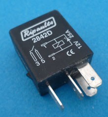
Terminals 3 and 5 look simple enough - they're for the switch
Terminals 1 and 2 however are the bit that sends the power to the thing you're controlling.
I assume terminal 1 would be connected to the fuse box and the battery (via ignition key for most things) and terminal 2 would go to the thing I'm controlling - the load (such as a fog light)
The thing that's causing a bit of confusion is that unlike most diagrams for a diode the diagram on the outside of the relay has the anode (+) on the blocked side of the diode diagram...
(I guess this is an indication I need to go back to the www school of finding stuff out - but I thought I'd ask here just in case I've got the wrong end of the stick and end up convincing myself regardless)