Army;
Sorry, but if you were to hook it up the way you explain, it wouldn't work (Explanation: The circuit elements pictured on relay show what is
inside relay, not how it should be connected externally!)...so terminals 3, 5 are the high current contacts which should be wired in series with high current load this relay is intended to control, and terms 1 and 2 are the coil whose current is controlled by the dashboard switch...the switch can either supply a connection to power (referred to as high side switching, with other side of coil connected to chassis/power return) OR it can supply a connection to chassis (referred to as low side switching, with other side of coil connected to power). The relay doesn't know or care...it only knows coil current is flowing, or none is flowing, so this gives installer some wiring options.
When there is a diode included (for the purpose of clamping voltage upon opening the circuit and breaking current flow, thus quenching switch contact arcing...preventing a pop on an AM radio is only a secondary benefit) polarity must be observed, and it should be positive on the Cathode (pin 1).
Example for wiring Fog Lights with automatic enabling at Lo-Beam only (if diodes were present, Cathodes would be on relay term 86 and 30/51):
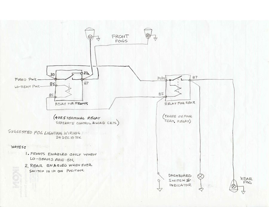
Cheers
PS: I also recommend you consider adding an Ignition Slave Relay to not pass current of additional Ign powered loads through the poor Ign Switch! See:
http://www.sw-em.com/Ignition_Slave_Relay.htm