
|
|||||||
| PV, 120 (Amazon), 1800 General Forum for the Volvo PV, 120 and 1800 cars |
 Information
|
|
Air in cooling systemViews : 2737 Replies : 28Users Viewing This Thread : |
 |
|
|
Thread Tools | Display Modes |
 Jan 16th, 2017, 19:23
|
#11 |
|
Junior Member
Last Online: Jul 27th, 2017 07:02
Join Date: Oct 2016
Location: Bournemouth
|
Also to confirm hose flow, I have it from block to heater control valve to heater core and back to cylinder head.
|

|

|
|
Jan 17th, 2017, 02:33
|
#12 |
|
Master Member
Last Online: Yesterday 15:09
Join Date: Oct 2013
Location: Alberta
|
Re: Ron's Diagram--Doesn't the heater circuit go to the heater valve before the heater core? At least it does on my 71e.
|
|
|
|
|
Jan 17th, 2017, 13:53
|
#13 | |
|
Member
Last Online: Jan 23rd, 2024 07:52
Join Date: Nov 2010
Location: Cape Town
|
Quote:
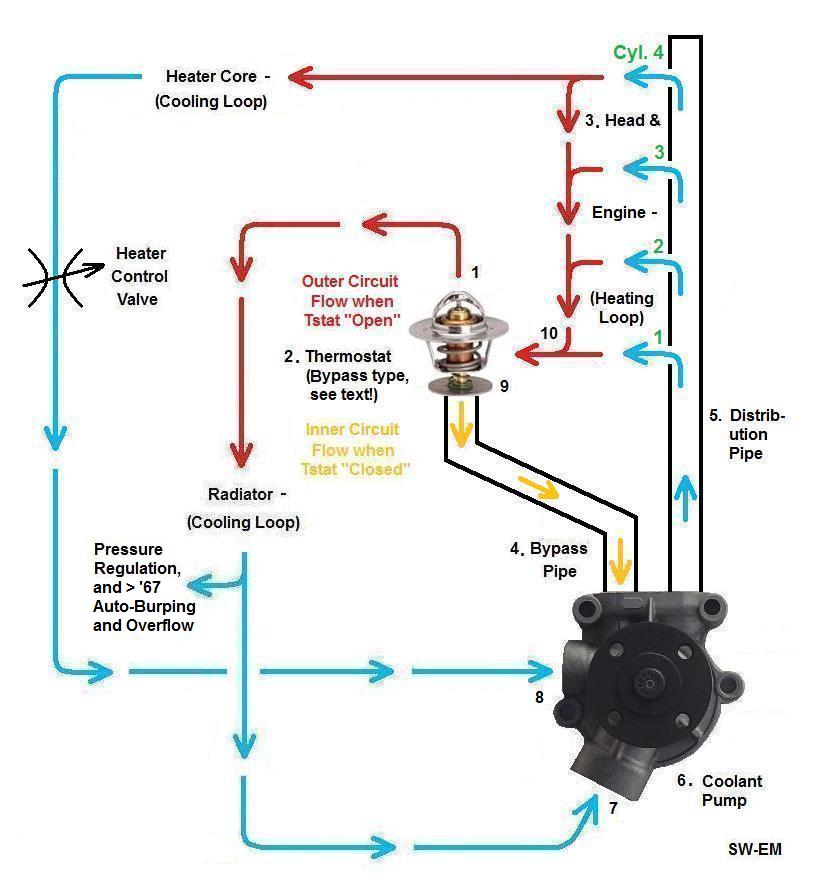
In mine (Amazon, B20) the arrangement is, going along the direction of coolant flow: Back of block (elbow) to top connection of heater valve (bent part); bottom connection of heater valve (straight part) to bottom connection of heater core; top connection of heater core to pump inlet (via metal tube along the side of the block). This seems to differ from Rons schema (where the core comes first and then the valve), although I cant see that the order of core and valve can make any difference to the way the system works. |
|
|
|
|
|
Jan 17th, 2017, 16:01
|
#14 |
|
Premier Member

Last Online: Today 20:51
Join Date: Jul 2007
Location: Connecticut, USA
|
...are you saying I got it wrong? (...I don't mind being corrected...peer review is good!)...so I'll have to double check...it is a series circuit so as far as flow and flow restriction goes, it wouldn't really matter functionally, and it could vary with models.
Cheers |

|
|
|
Jan 18th, 2017, 11:03
|
#15 | |
|
Member
Last Online: Jan 23rd, 2024 07:52
Join Date: Nov 2010
Location: Cape Town
|
Quote:
The heater should come first and then the valve. At least for the 122S, according to the gcp catalog. For the B20: http://weblisher.textalk.se/gcp/2016...0&noConflict=1 and go to page 433. It makes sense to have the valve in a cooler rather than hotter part of the circuit. And in case were talking about an 1800. See: http://weblisher.textalk.se/gcp/2016...0&noConflict=1 and go to page 433. Maybe Phid can figure it out from here. I cant. Presumably the same order is required: Heater core first and then the valve. |
|
|
|
|
|
Jan 18th, 2017, 13:04
|
#16 |
|
Junior Member
Last Online: Jul 27th, 2017 07:02
Join Date: Oct 2016
Location: Bournemouth
|
Thanks for that - and yes mine is therefore wrong. Probably not the cause of my [cars] trapped air but worth getting right.
|
|
|
|
|
Jan 18th, 2017, 14:45
|
#17 |
|
Master Member
Last Online: Yesterday 15:09
Join Date: Oct 2013
Location: Alberta
|
Looks like mine is wrong too, the factory preformed heater hoses seem to work either way! The angled nipple at the back of the head is angled to take the long hose to the valve first however. In any case the heater works just fine and I can turn the heat on and off at will with immediate response, so I'll leave it as is.
Sorry for the confusion. |
|
|
|
|
Jan 20th, 2017, 09:12
|
#18 | |
|
Premier Member

Last Online: Oct 23rd, 2023 21:39
Join Date: Apr 2007
Location: EXETER
|
Quote:
With reference to that there distribution pipe, that is the one that I am referring to breaking up. That's the one that runs internally. Surely if that's bad, coolant can't get to the back of the head (heater), no? Additionally, I am almost sure (woolly memory here) that our Derek UK once put up a photo of how that pipe must be properly inserted into the head. Derek, am I barking up the wrong tree?! All said, it's more than important to make sure there's no air in the system before looking any further!
__________________
2006 XC70 D5 Manual 1968 Amazon Estate, B18A + Overdrive 2019 V60 D3 Momentum Pro Manual 1970 Amazon 2-Door 1970 142DL |
|
|
|
|
|
Jan 20th, 2017, 12:34
|
#19 |
|
VOC Member

Last Online: Jun 22nd, 2024 14:01
Join Date: Jul 2006
Location: Chatham
|
Yes I did put up a post with pictures of the brass cooling tube. Currently I can only go back 500 posts/1st April 2016 when looking for a link to it. I've asked the mods about it. The pipe post was a further back than that.
This is rarely a problem. It is peened into place but if that was badly done it might allow the pipe to rotate a bit. An odd bit of something, maybe a piece of rubber from a dodgy old hose might also possibly get into the pipe and block it partially somewhere between the front and the back. Did find this........ http://www.volvoforums.org.uk/showth...rass+pipe+head |
|
|
|
|
Jan 20th, 2017, 14:10
|
#20 |
|
Premier Member
Last Online: Today 20:51
Join Date: Jul 2007
Location: Connecticut, USA
|
guys;
The Dist Pipe is not round in cross section, but sort-of keyhole shaped, so under normal conditions, it cant really turn (very much) out of axial position...I've collected all I could about the pipe (including pix) here: http://www.sw-em.com/Coolant_Distrib...Pipe_Notes.htm Cheers Last edited by Ron Kwas; Jan 20th, 2017 at 15:26. |
|
|
|
|
| Currently Active Users Viewing This Thread: 1 (0 members and 1 guests) | |
|
|


 Linear Mode

