
|
|||||||
| PV, 120 (Amazon), 1800 General Forum for the Volvo PV, 120 and 1800 cars |
 Information
|
|
1961 Volvo PV544 in HollandViews : 88270 Replies : 750Users Viewing This Thread : |
 |
|
|
Thread Tools | Display Modes |
 Feb 12th, 2019, 14:08
|
#601 |
|
Master Member
Last Online: Yesterday 15:06
Join Date: Oct 2013
Location: Alberta
|
Are you actually looking for a connector enclosure? When I read junction box I think of a box with terminals to connect wires.
|

|

|
|
Feb 12th, 2019, 14:54
|
#602 | |
|
marches on his stomach
Last Online: Feb 11th, 2022 03:15
Join Date: Jan 2018
Location: Somewhere in the Netherlands
|
Quote:
I was thinking along the lines of some sort of branded automotive thing - such as an empty can of oil =>  Thing is I'd rather have a larger screw lid so I don't have to modify the tin too much. The plan would be to make a bracket and some form of strap to hold the box in position - I reckon it would be nice to see something that's automotive and has been reused...
__________________
1961 Volvo PV544 the quick and easy in between project(!) 1981 Mercedes 300D <=> 230 diesel to petrol conversion project 1965 Series 2a Station Wagon mega build 1992 Mercedes 190E The car that works! 
|
|
|
|
|
|
Feb 12th, 2019, 16:01
|
#603 |
|
Master Member
Last Online: Yesterday 15:06
Join Date: Oct 2013
Location: Alberta
|
Something like this? Modifications required for the wires. Maybe a U shaped slot at each end with a rubber grommet around the wire.
http://www.anboxelectric.com/sale-79...enclosure.html |
|
|
|
|
Feb 13th, 2019, 04:42
|
#604 | |
|
marches on his stomach
Last Online: Feb 11th, 2022 03:15
Join Date: Jan 2018
Location: Somewhere in the Netherlands
|
Quote:
__________________
1961 Volvo PV544 the quick and easy in between project(!) 1981 Mercedes 300D <=> 230 diesel to petrol conversion project 1965 Series 2a Station Wagon mega build 1992 Mercedes 190E The car that works!
|
|
|
|
|
|
Feb 13th, 2019, 15:02
|
#605 |
|
marches on his stomach
Last Online: Feb 11th, 2022 03:15
Join Date: Jan 2018
Location: Somewhere in the Netherlands
|
FOR i = 1 TO INF Figure out the colour and size of the wire Cut wire to length Find correct connector Strip end of wire to suit connector Apply magic goo to end of wire Fit wire and connector in crimping pliers Crimp connector Check connector is properly crimped and that the fixing for the insulation also came good Cut correct sized heat shrink to size Fir heat shrink over new joint Heat heat shrink Stick connector in correct hole i = i + 1 END i Flippin' 'eck!
__________________
1961 Volvo PV544 the quick and easy in between project(!) 1981 Mercedes 300D <=> 230 diesel to petrol conversion project 1965 Series 2a Station Wagon mega build 1992 Mercedes 190E The car that works!
|
|
|
|
|
Feb 15th, 2019, 14:48
|
#606 |
|
marches on his stomach
Last Online: Feb 11th, 2022 03:15
Join Date: Jan 2018
Location: Somewhere in the Netherlands
|
I've got some gucci little micro relays that have a diode in them to help stop interference with electronics when the relays operate
These things come with a warning about polarity - unfortunately the ID numbers on the terminals are the normal numbers used on most relays - so I'm in a bit of a fog. 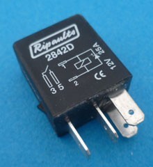 Terminals 3 and 5 look simple enough - they're for the switch Terminals 1 and 2 however are the bit that sends the power to the thing you're controlling. I assume terminal 1 would be connected to the fuse box and the battery (via ignition key for most things) and terminal 2 would go to the thing I'm controlling - the load (such as a fog light) The thing that's causing a bit of confusion is that unlike most diagrams for a diode the diagram on the outside of the relay has the anode (+) on the blocked side of the diode diagram... (I guess this is an indication I need to go back to the www school of finding stuff out - but I thought I'd ask here just in case I've got the wrong end of the stick and end up convincing myself regardless)
__________________
1961 Volvo PV544 the quick and easy in between project(!) 1981 Mercedes 300D <=> 230 diesel to petrol conversion project 1965 Series 2a Station Wagon mega build 1992 Mercedes 190E The car that works!
|
|
|
|
|
Feb 15th, 2019, 16:43
|
#607 |
|
Premier Member

Last Online: Today 03:33
Join Date: Jul 2007
Location: Connecticut, USA
|
Army;
Sorry, but if you were to hook it up the way you explain, it wouldn't work (Explanation: The circuit elements pictured on relay show what is inside relay, not how it should be connected externally!)...so terminals 3, 5 are the high current contacts which should be wired in series with high current load this relay is intended to control, and terms 1 and 2 are the coil whose current is controlled by the dashboard switch...the switch can either supply a connection to power (referred to as high side switching, with other side of coil connected to chassis/power return) OR it can supply a connection to chassis (referred to as low side switching, with other side of coil connected to power). The relay doesn't know or care...it only knows coil current is flowing, or none is flowing, so this gives installer some wiring options. When there is a diode included (for the purpose of clamping voltage upon opening the circuit and breaking current flow, thus quenching switch contact arcing...preventing a pop on an AM radio is only a secondary benefit) polarity must be observed, and it should be positive on the Cathode (pin 1). Example for wiring Fog Lights with automatic enabling at Lo-Beam only (if diodes were present, Cathodes would be on relay term 86 and 30/51): 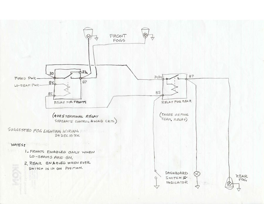 Cheers PS: I also recommend you consider adding an Ignition Slave Relay to not pass current of additional Ign powered loads through the poor Ign Switch! See: http://www.sw-em.com/Ignition_Slave_Relay.htm Last edited by Ron Kwas; Feb 15th, 2019 at 17:45. |
|
|
|
| The Following User Says Thank You to Ron Kwas For This Useful Post: |
|
Feb 16th, 2019, 04:43
|
#608 |
|
marches on his stomach
Last Online: Feb 11th, 2022 03:15
Join Date: Jan 2018
Location: Somewhere in the Netherlands
|
Thanks Ron - I think I got me numbers muddled up
When looking at the relay it is clear to see which pins are for the switch and the load (wider pins are for the load) I was a bit more worried about the polarity (I dodn't want to mess up the diode) but can now see what I'm meant to do - thanks The ignition switch saving advice is something I'm planning to adopt
__________________
1961 Volvo PV544 the quick and easy in between project(!) 1981 Mercedes 300D <=> 230 diesel to petrol conversion project 1965 Series 2a Station Wagon mega build 1992 Mercedes 190E The car that works!
|
|
|
|
|
Feb 16th, 2019, 10:38
|
#609 | |
|
Junior Member
Last Online: Jun 16th, 2024 16:18
Join Date: May 2010
Location: Shrewsbury
|
Quote:
Shame fuse boxes are rectangular as if they were round I reckon an old Castrol grease tub would have been a good option giving you a screw top but being plastic so the threads don't corrode ust as you need to get in. On my Defender seat box I installed a circular screw thread locker opening (similar to this, others are available, https://www.ebay.co.uk/i/162569648620?chn=ps) which you could install to any type of right sized container. Apologies if this is just useless waffle. (Gets me closer to my 30 posts after spending time writing a PM today and finding I can't send it). |
|
|
|
|
|
Feb 16th, 2019, 13:26
|
#610 |
|
arcturus

Last Online: Yesterday 07:15
Join Date: Mar 2006
Location: Sagres Portugal
|
Apologies if this is just useless waffle. (Gets me closer to my 30 posts after spending time writing a PM today and finding I can't send it).
If you send all the regular contributors to this forum a belated "happy Christmas" greeting you will soon reach your 30 
__________________
life's too short to drink bad wine
|
|
|
|
| The Following User Says Thank You to arcturus For This Useful Post: |
|
| Currently Active Users Viewing This Thread: 1 (0 members and 1 guests) | |
|
|


 Linear Mode

