
|
|||||||
| 700/900 Series Articles How to's and Guides for the P700/900 series. |
 Information
|
|
960 / V90 parking brake cable R&RViews : 14872 Replies : 11Users Viewing This Thread : |
 |
|
|
Thread Tools | Display Modes |
 Nov 2nd, 2013, 17:50
|
#1 |
|
Junior Member
Last Online: Jun 28th, 2017 04:13
Join Date: Oct 2013
Location: Ottawa
|
Hi all,
Well, the DPO of my '96 960 cut the cables for the parking brake when they seized (probably due to lack of use).  I need working p-brakes for my safety check (MOT), so it's a must-fix. The stealership quoted me approx. $500 (~250 pounds) for just the parts; I'm guessing it would have been more than twice that for labour. So, having peered into the depths of my wallet, I decided to do the job myself. I used tascaparts.com - for those of you in NA, these guys are fantastic. All OE Volvo-branded parts, and cheapest around. They had everything I needed, shipped to me, in four days. Total cost, ~$150 for all three cables, assorted hardware bits & bobs, new rear pads and p-brake drums. I have just started on the repair; I'll dig out my camera and try to take some snaps as I go. |

|

|
|
Nov 2nd, 2013, 17:56
|
#2 |
|
Junior Member
Last Online: Jun 28th, 2017 04:13
Join Date: Oct 2013
Location: Ottawa
|
PREP
1) Loosen all rear lug nuts 2) Chock front wheels 3) Jack up car (I suggest under rear A-arms) and use axle stands (I suggest under rear suspension assembly / cross-member). Get it as high as you can. 4) Remove rear wheels. 5) Give all fittings (caliper bolts, p-brake cable ends) a shot of penetrant. Don't use WD40; PB Blaster is my potion of choice. 6) Go inside. Make tea; start a repair thread.  More to follow. |
|
|
|
|
Nov 2nd, 2013, 22:42
|
#3 |
|
Junior Member
Last Online: Jun 28th, 2017 04:13
Join Date: Oct 2013
Location: Ottawa
|
OK, here we go...
DISASSEMBLY 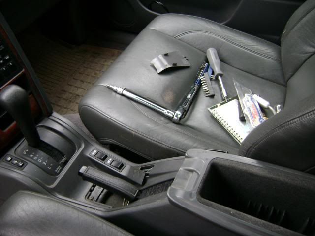 For the interior bits, you'll need torx screwdrivers (T15, 20, 25), a small flathead screwdriver (for prying up trim), and sockets (13mm?) for the rear seat brackets. 1) Remove the centre console. See instructions here: http://atthetipwebs.com/technologyin...ock_repair.htm See also: http://img.photobucket.com/albums/v6...960shifter.jpg (thanks to Tech on volvoforums) The screws directly under the pbrake handle are easy to spot. The ones under the ashtray will want to drop; careful! And when you think you've taken everything out, but the front still won't move... 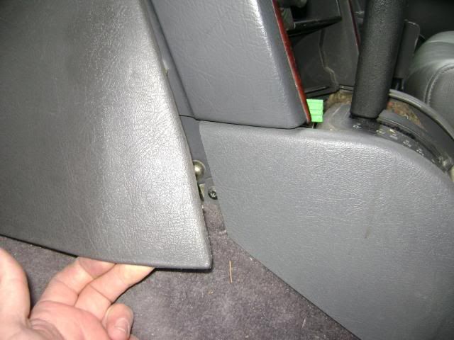 I lifted up the 'insert' first; pushed through all the switches, and then disconnected them from above. Some of this may not strictly be necessary, but some of my dash & accessory bulbs have burned out, and I view this as a good opportunity to change them all. 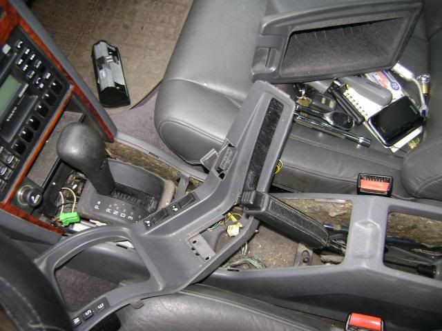 With everything undone, the whole console can be lifted out of the way, and the pbrake mechanism is exposed. 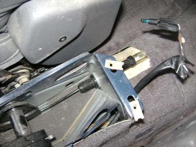
|
|
|
|
|
Nov 2nd, 2013, 22:57
|
#4 |
|
Junior Member
Last Online: Jun 28th, 2017 04:13
Join Date: Oct 2013
Location: Ottawa
|
DISSASEMBLY (CONT'D)
2) Remove the lower cushions of the rear seats. This is done by folding them upward (as though to fold down the seat backs), and then giving a sharp tug straight up. (I had no idea this could be done! Very cool.) 3) We need to access the hole in the bulkhead, through which the pbrake cable passes. So, loosen (or remove) all three lower cushion brackets, and peel back the carpet (and reinstall brackets so they don't get lost). 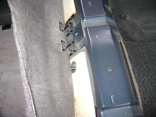 Here is a view from the front seat facing backward. You can see the pbrake assembly, and the hole and rubber grommet are just visible. 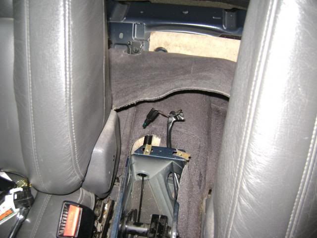 4) Disengage the pbrake cable from the handle (there is a small metal tab that is folded up to allow the cable end to disengage). 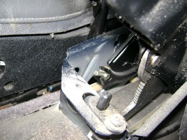 5) Unthread the plastic nut from the metal housing, then push the female portion through to disengage the cable from the housing altogether. 6) Starting in the back seat area, pull the brake cable backward under the carpet until it is all exposed at the bulkhead area. 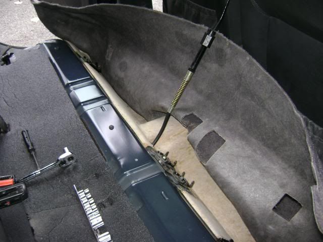
|
|
|
|
|
Nov 2nd, 2013, 23:33
|
#5 |
|
Junior Member
Last Online: Jun 28th, 2017 04:13
Join Date: Oct 2013
Location: Ottawa
|
DISSASSEMBLY (CONT'D) - BRAKES
As previously mentioned, I have the car up high, on jackstands. 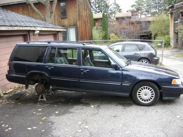 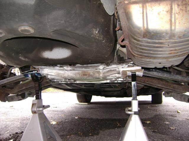 1) The rotors are held on by the locator pin (seen at six o'clock here), which is removed using a 10mm deep socket. 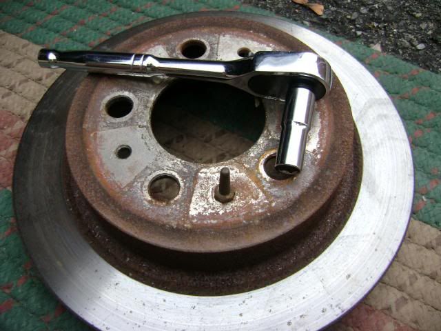 2) Each caliper is held on by two bolts, from behind. Mine were 15mm (p/side) and one 15mm, one 16mm (driver's side). Very odd; yours may be different. In any case; unbolt, and hang the caliper off a loop of the rear spring (wire coathangers work well here). 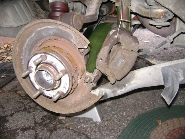 3) The pbrake drum assembly (retaining clip, spring, drums and spacer) can now be disassembled. I won't post photos here for bandwidth reasons, but they are in my album. I think it should be available to everyone; http://s10.photobucket.com/user/toso...?sort=6&page=1 4) Remove the retaining clip (behind the dust shield) and remove the outboard end of the parking brake cable (sheath and inner portion). 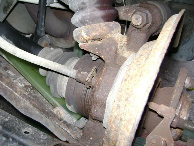 5) Remove the muffler (to allow access to the inner portion of the cable assembly) as follows. Loosening the exhaust clamp above the rear axle, p/side (a tight squeeze; 15mm, I think). unhook the muffler hangers (I chose to unhook the outboard rubber mount, and unbolt the inboard hanger assembly, 2x14mm nuts. The muffler should drop somewhat, and can now be wiggled from side to side until loose. Hint: I found it necessary to jack up the exhaust slightly, just in front of the axle (i.e. behind the resonator) to allow more room to drop the muffler. The inner workings of the pbrake cable assembly can now be accessed somewhat. View from outboard; 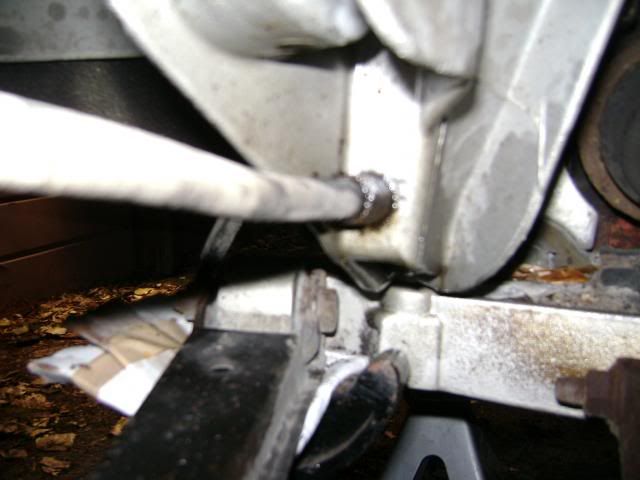 View from inboard; 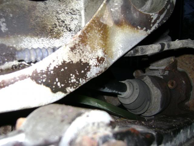 That's where I left it for the night; dosed everything with a shot of PB Blaster and put everything away. Back at it tomorrow. |
|
|
|
|
Nov 2nd, 2013, 23:42
|
#6 |
|
Still a learning member
Last Online: Aug 17th, 2022 18:49
Join Date: Apr 2012
Location: Ayrshire
|
Hello,
Fantastic write up  Cheers |
|
|
|
|
Nov 2nd, 2013, 23:58
|
#7 |
|
Junior Member
Last Online: Jun 28th, 2017 04:13
Join Date: Oct 2013
Location: Ottawa
|
Thanks Ov!
I probably should have posted it at the beginning, but the exploded diagram of the pbrake assembly (all 960 / v90 / s90 *with* multilink suspension) can be found HERE. HOWEVER, my car does not seem to have the brackets referred to as #25 on that diagram. Their function is served by the actual aluminium sub-assembly itself; the cable runs right through it, as those last two photos show. So I'm not sure whether Volvo didn't bother doing a separate diagram to show all variations, or... Here's hoping that the parts are correct, anyway. |
|
|
|
|
Nov 3rd, 2013, 04:52
|
#8 |
|
Junior Member
Last Online: Jun 28th, 2017 04:13
Join Date: Oct 2013
Location: Ottawa
|
On this diagram can anyone tell me whether later cars actually have part #25? (I haven't dropped the tank yet; it occurs to me that they may just be hidden somewhere out of sight. Do the cables run through the aluminium subframe (as pictured above) and then also through that bracket?
 I just haven't yet seen anything that looks like that. But then again, all the lines had been cut and were dangling, so... I just haven't yet seen anything that looks like that. But then again, all the lines had been cut and were dangling, so...
|
|
|
|
| The Following User Says Thank You to tosoutherncars For This Useful Post: |
|
Nov 3rd, 2013, 06:43
|
#9 |
|
VOC Member
Last Online: Apr 12th, 2024 13:08
Join Date: Aug 2006
Location: Hounslow West London
|
Excellent write up....keep it coming.
You will make your access much better by putting a jack under the spare wheel recess (a wood board across will spread the load; and leave the axel stands where they are), and jack the body up about 5" or 6" off the axel; you will be amazed how much easier it will be. Cheers. |
|
|
|
|
Nov 3rd, 2013, 23:01
|
#10 |
|
Junior Member
Last Online: Jun 28th, 2017 04:13
Join Date: Oct 2013
Location: Ottawa
|
OK, here we go; Day 2 of the Continuing Saga of the Non-Functioning Parking Brake!
I will start by saying this, in reference to my earlier question: THE EXPLODED DIAGRAM REFERENCED ABOVE IS *NOT* ACCURATE FOR LATER CARS. On my car, there is no separate bracket (part labeled #25); the aluminium sub-frame serves as the inboard terminal point for the outer casing. No clip (part #24) is used on the inboard end, either. The anodized metal cable end is a friction fit. FINAL DISASSEMBLY Before going any further, I laid out the new parts, to get an idea of layout. Cable ending '32 is left side; '33 is right side. In the picture below, we are standing behind the car, so to speak. 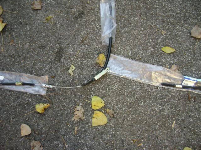 It hurts my brain a bit, but I get it... the main cable pulls on the left-side brake assembly. That has the effect of wanting to pull the centre point (and therefore the anodized bracket) to the left; and *that*, in turn, puts an equal and opposite pull on the right-side assembly. So, I disconnected the middle exhaust / resonator at the cat. (Had to drill out one of the two bolts, which was rusted solid.) I didn't (couldn't) remove that portion of the exhaust, as it's trapped by the rear axle; but unbolting it at both ends lets you move it around as needed. And trust me, it's needed. Next, I slacked all the bolts I could find that hold up the gas tank. Chief here was the bolt (attached to the exhaust hanger bracket) on the right outboard side of the tank. As well, the bolts holding on the retaining straps and retaining strap bracket. Sorry, no photos. Loosening all the bolts dropped the tank maybe 2"; just enough to get at the cable, which (again) runs down the right outboard side of the tank. Next, you have to disconnect the P-shaped clamp (part #20 on diagram) which is at the highest part, directly over the right axle. It is almost invisible; here is the best shot I could get of it, from the rear (with muffler removed). 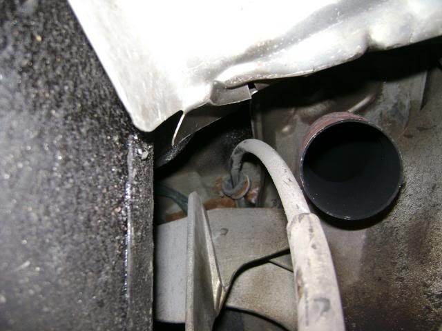 With the mid-pipe pushed aside, remove with a LONG extension with a 8mm (I think) bit from directly underneath. Easier than trying to get your hand up there. It was then time to remove the cable. I duct-taped some cord to the end, before pulling / pushing it through. (This is the 'after' picture.) 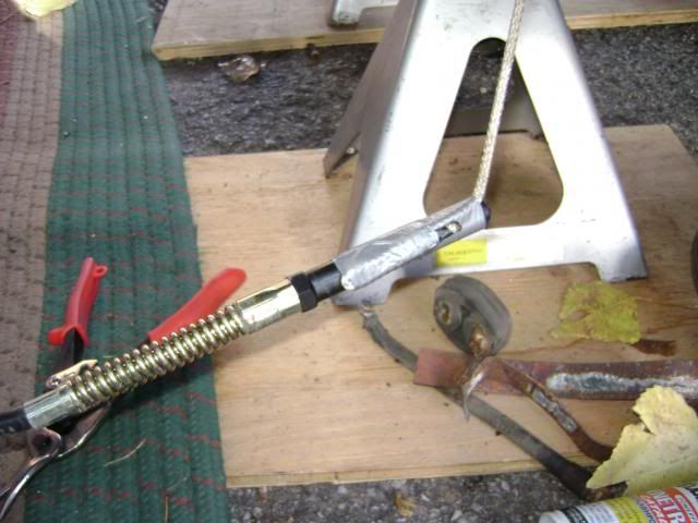 REASSEMBLY BEGINS CONTROVERSIAL BIT: I really didn't want to bother trying to push the rubber grommet in from underneath. Now, my original grommet was in good condition, so I had a spare, and decided to experiment. Step one: slice grommet down the middle. Step two: fish the cable back in from underneath, using rope. (Easy breezy.) Step three: from the comfort of your back seat, install sliced-up grommet from above. Make sure 'slice' is on the side opposite where the cable tends to press. Again, easy as pie. 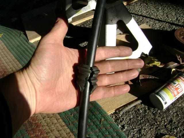 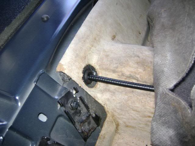 I am *sure* that my little workaround will not spin in place , which would then allow the cable to be damaged by the metal chassis. But as always, YMMV. Reinstalled the new P-clip above the axle, with new nut (all parts recommended by the technical notes). REASSEMBLY - REAR CABLE, RIGHT SIDE 1) Clean out holes in knuckle and aluminium subframe. 2) Install hose at both ends. It is a push fit; no disassembly required, the ends (and rubber gaiter) fit through the holes. I didn't use anti-seize here - in retrospect, I think I should have. 3) Install new retaining clip (part #24) behind dust shield. REASSEMBLY - PARKING BRAKE DRUMS 1) Spray down dust plate / assembly with brake cleaner. Spray rotors, paying particular attention to inner drum surfaces. 2) Install spreader assembly (part #34/35) onto new cable end. (Use left side as guide, but remember it's a mirror image). 3) Reassemble new drums. Ends with tapered metal go toward the spreader assembly. Fixed spacer goes at the other end. 4) Install thick curved metal spring (two or three flathead screwdrivers needed here, to pry.) 5) Install retaining clip to hold down main spring. 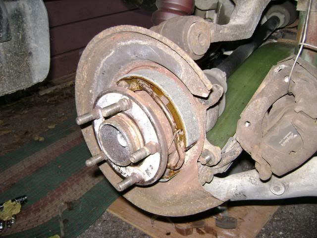 6) Re-check; then reinstall rotor, making sure to use anti-seize on surfaces that contact the hub. Well, that's where I got to today; I'm hoping to finish tomorrow. Still to do; pbrake on the left side, brake pads (both sides), complete reassembly, and adjust everything. My only concern is that I don't have a dial gauge, to measure run-out on the rotors when reinstalling. However, I'm putting the old ones back on; guess I'll chance it. If I end up with pulsating brakes, I'll have to pull it back apart and (either) rotate them or (more likely) install new rotors. But that's a 30 minute job, if everything else is done. So for now, I just want to get it all back together, and past the MOT. |
|
|
|
|
| Currently Active Users Viewing This Thread: 1 (0 members and 1 guests) | |
|
|


 Linear Mode

