
|
|||||||
| 700/900 Series General Forum for the Volvo 740, 760, 780, 940, 960 & S/V90 cars |
 Information
|
|
Strange Dash Lighting Issue - wiring diagrams?Views : 2898 Replies : 29Users Viewing This Thread : |
 |
|
|
Thread Tools | Display Modes |
 Dec 12th, 2014, 07:56
|
#11 |
|
Senior Member
Last Online: Aug 30th, 2021 08:18
Join Date: Jan 2010
Location: Stroud
|
KBB - Good point, well made!
Pete940, what KBB suggests is a very effective method of identifying where a fault in an electrical circuit is. The reason it is necessary is that defective parts can sometimes show a nominally correct value of resistance when no current is flowing but another very different resistance when subjected to an electrical load. I'll have a go at outlining the voltage testing method... A voltage is always measured at one point (node) in a circuit, with respect to (wrt) another. Although voltage is often measured with respect to chassis, for fault finding purposes it is useful to measure voltages with respect to other nodes in the circuit as well. (A node is where two or more conductors join.) If we consider the dash lighting circuit as a series of nodes we might end up with the following list: Battery+(1), Wire_Start(2), Wire_End(3), Switch_In(4), Switch_Out(5), Wire_Start(6), Wire_End(7), Rheostat_In(8), Rheostat_Out(9), Wire_Start(10), Wire_End(11), Paralleled_Bulbs_In(12), Paralleled_Bulbs_Out(13), Wire_Start(14), Wire_End(15), Chassis(16). The intended operation of the circuit is that almost no voltage is dropped across the wires and switch, some is dropped across the rheostat and the majority is dropped across the bulbs. If the circuit was operating correctly and you took voltage measurements across each pair of nodes in turn, you might end up with results like this: 1 wrt 2 = 0.1V 2 wrt 3 = 0.2V 3 wrt 4 = 0.1V 4 wrt 5 = 0.1V 5 wrt 6 = 0.1V 6 wrt 7 = 0.2V 7 wrt 8 = 0.1V 8 wrt 9 = 2.8V 9 wrt 10 = 0.1V 10 wrt 11 = 0.2V 11 wrt 12 = 0.1V 12 wrt 13 = 7.5V 13 wrt 14 = 0.1V 14 wrt 15 = 0.1V 15 wrt 16 = 0.2V 1 wrt 16 = 12.0V However, if you took the measurements and they came out like this: 1 wrt 2 = 0.0V 2 wrt 3 = 0.0V 3 wrt 4 = 0.0V 4 wrt 5 = 0.0V 5 wrt 6 = 0.0V 6 wrt 7 = 0.0V 7 wrt 8 = 0.0V 8 wrt 9 = 0.3V 9 wrt 10 = 0.0V 10 wrt 11 = 0.0V 11 wrt 12 = 0.0V 12 wrt 13 = 0.5V 13 wrt 14 = 0.0V 14 wrt 15 = 0.0V 15 wrt 16 = 11.2V 1 wrt 16 = 12.0V You would have identified that the earthing point was at fault because there should be almost no voltage dropped from node 15 to node 16 yet 11.2V was measured. Hope this helps! Boots.
__________________
2007 V70 D5 SPORT 150k 1997 V70 2.5TDI 290k - Sent on to pastures new! |

|

|
| The Following User Says Thank You to B00TS For This Useful Post: |
|
Dec 12th, 2014, 08:18
|
#12 |
|
Ideal Volvo
Last Online: Today 21:45
Join Date: Aug 2012
Location: Haydock
|
Excellent information. Very much appreciated.
|

|
|
|
Dec 13th, 2014, 14:20
|
#13 |
|
Ideal Volvo
Last Online: Today 21:45
Join Date: Aug 2012
Location: Haydock
|
4 pins of the 14 pin socket concern the main dash lights, apparently.
Pins 13 and 12 supply 12v. Pin 8 supplies whatever voltage comes out of the rheostat (9v in my case). Pin 5 goes to ground. Using the meter on pins 12 and 5 of the socket (with socket not attached to dash) gives 12v. Using the meter on positions 12 and 5 of the printed circuit board (immediately below the socket) gives 0v. How can the voltage from pin 12 become zero on the PCB? Can anyone explain what I should conclude from this? Pins 12 and 13 go firstly to the little voltage regulator block thingy on the back of the dash (or whatever that thing is). See pics below. The main dash lights are in the 4 black plastic holders and also the highest central blue holder. 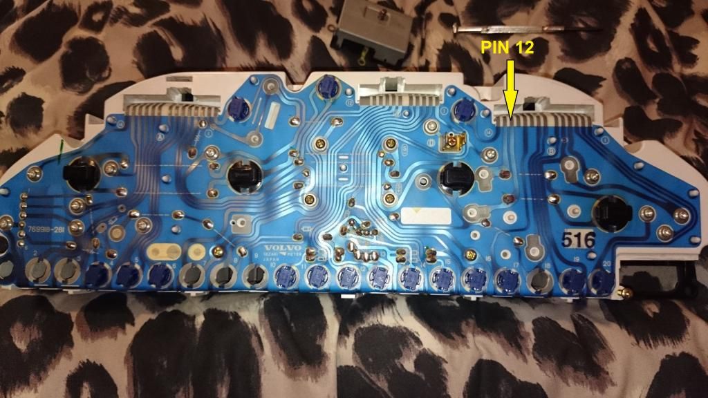 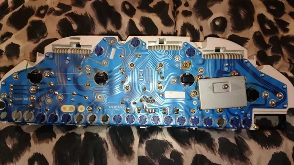
|
|
|
|
|
Dec 13th, 2014, 15:02
|
#14 |
|
Master Tech
Last Online: May 18th, 2020 10:57
Join Date: Dec 2006
Location: On Contract Dubai Automotve Technical Academy
|
Pete,
Try this quick test, with the connectors in place and power on. Take a pin/needle solder a 1m jumper wire, insert the needle down the back of the wire in the connector at B8 and ground the other end and get back to us This will by-pass the dropping resistors in the variable rheostat. |
|
|
|
| The Following User Says Thank You to KBB For This Useful Post: |
|
Dec 13th, 2014, 16:52
|
#15 |
|
Ideal Volvo
Last Online: Today 21:45
Join Date: Aug 2012
Location: Haydock
|
Just tried it. Now got 12v on the PCB at position 12.
No dash lights but I'm guessing that wasn't the point of the experiment. So does that tell us the dropping resistors are bad, or just something in that little circuit? Cheers. |
|
|
|
|
Dec 13th, 2014, 17:56
|
#16 |
|
Master Tech
Last Online: May 18th, 2020 10:57
Join Date: Dec 2006
Location: On Contract Dubai Automotve Technical Academy
|
Pete, The voltage you are seeing on B12 is the ground side of all the other instrumentation bulbs and at this point are yet to flow through the fixed PCB stat and then onto the variable resistor and then to ground as these are working fine along with the warning lights then all that side of things are good along with the PCB stat. The 5 instrument bulbs look to have their own power supply via B13 and then ground in series first through the fixed PCB stat and then finally through the variable stat.
The are 2 areas I would now focus on first and that is to confirm the power supply to pin B13 will hold up to load. Disconnect connector B and make a simple test bulb a side light would be ideal as it will pull a couple of amps with your DVM set to the 20v range power on the vehicle place the ground side of the test bulb to known good ground along with meter ground lead, place red lead on connector B13 and note the voltage keep in on B13 and then place the bulb positive side on the red pin and see if the voltage stays up, it should drop no more than 0.2v.also check the female pin B13 in the connector for over splaying as this can significantly reduce the contact area on the male pin in the binnacle and cause a voltage drop. If this tests out good then we will move on to bench testing and circuit proving on the PCB. |
|
|
|
|
Dec 14th, 2014, 12:28
|
#17 |
|
Ideal Volvo
Last Online: Today 21:45
Join Date: Aug 2012
Location: Haydock
|
Using a 21W bulb gives a voltage drop of 0.28V. The ground I used was just a large metal bracket, but that should be ok right?
|
|
|
|
|
Dec 14th, 2014, 13:16
|
#18 |
|
Master Tech
Last Online: May 18th, 2020 10:57
Join Date: Dec 2006
Location: On Contract Dubai Automotve Technical Academy
|
Yep chassis ground is good as the bulb would have lit up. 21w bulb on a 12v ish circuit would draw little under 2 amps, a drop of 0.28 of a volt is fine so the supply from fuse 21 to pin B13 is good under load. Did you manage to examine the female pin of B13 just to ensure that it is not overly splayed?
Bench testing would be next, have you got one of those automotive test light's like a screw driver with a bulb in the clear handle and about 2 feet of flex with a crock clip on the end? will also need a 12v battery. |
|
|
|
|
Dec 14th, 2014, 13:36
|
#19 |
|
Ideal Volvo
Last Online: Today 21:45
Join Date: Aug 2012
Location: Haydock
|
I don't see a male and female connection as such, but I did check that the socket connections were not bent etc. The socket has prongs that simply push against the PCB.
Think I could use something cheap like this? http://www.ebay.co.uk/itm/CAR-LIGHT-...item27d0757330 Slight problem is getting a 12v battery. I'll see what I can do. |
|
|
|
|
Dec 20th, 2014, 17:45
|
#20 |
|
Ideal Volvo
Last Online: Today 21:45
Join Date: Aug 2012
Location: Haydock
|
What's the process for bench testing? I've got my testing equipment now. I was thinking about starting off by using the test lamp to check the grounds at the soldered points for each bulb, if that's possible.
|
|
|
|
|
| Tags |
| dash, dashboard, lights |
| Currently Active Users Viewing This Thread: 1 (0 members and 1 guests) | |
|
|


 Linear Mode

