
|
|||||||
| 700/900 Series General Forum for the Volvo 740, 760, 780, 940, 960 & S/V90 cars |
 Information
|
|
Help neededViews : 2799 Replies : 71Users Viewing This Thread : |
 |
|
|
Thread Tools | Display Modes |
 May 16th, 2018, 09:34
|
#21 |
|
Master Member
Last Online: Today 15:32
Join Date: Feb 2006
Location: Amersfoort (NL)
|
If the ICV does not work properly, also check the TPS on the throttle housing. When idling (not touching the throttle pedal), the orange wire (pin 1) should be earthed via the black wire on pin 2.
|

|

|
|
May 16th, 2018, 09:41
|
#22 |
|
Member
Last Online: Apr 19th, 2024 06:45
Join Date: Jan 2018
Location: Warminster
|
Thanks to all for your help & information. Il try another icv & see what happens. Spose this should teach me a lesson with buying cheaper parts as its the only non genuine part that i have replaced thats failed.
|

|
|
|
May 16th, 2018, 09:44
|
#23 |
|
Member
Last Online: Apr 19th, 2024 06:45
Join Date: Jan 2018
Location: Warminster
|
Tps shows increasing voltage when back probed and put through movement. But i do have a spare tps in my box should the original fail.
|
|
|
|
|
May 16th, 2018, 09:46
|
#24 |
|
Senior Member
Last Online: Today 07:22
Join Date: Jul 2012
Location: Northwich
|
It might not have failed, if you still have the original clean it out with something to break down any oil in it and then give it a go again. The originals rarely fail,they are also a generic Bosch part so are used on other makes and models of car.
__________________
940 B230FT |
|
|
|
|
May 16th, 2018, 09:54
|
#25 |
|
Member
Last Online: Apr 19th, 2024 06:45
Join Date: Jan 2018
Location: Warminster
|
Yeah im just about to try the original one just to see if it clears the code however i think this one is toast. Neither of them are seized though and go through full movement.
|
|
|
|
|
May 16th, 2018, 10:12
|
#26 | |
|
Master Member
Last Online: Oct 8th, 2022 22:22
Join Date: Sep 2016
Location: Auckland
|
Quote:
7/75 is the bulb failure sense resistor. Its shown simplified. In other diagrams, it is shown as a part of other bulb circuits. Its shown in the electrical distribution box on page 126 (just next to the fuel pump relay position) The dim/dip voltage is electronically reduced by the electronic regulator component 2/3. Unless the system had some form of modification or downgrade in later years, I don't know what the long resistor does, but its not dim/dip voltage reduction. Last edited by aardvarkash10; May 16th, 2018 at 10:20. |
|
|
|
|
| The Following User Says Thank You to aardvarkash10 For This Useful Post: |
|
May 16th, 2018, 10:44
|
#27 |
|
Premier Member
Last Online: Today 08:43
Join Date: May 2012
Location: Lakenheath
|
You're right Ash, i was still half asleep when i added that, maybe why i TARFU'd it!
 *** EDIT *** i have seen a dim-dip resistor used on other cars including Volvos so maybe they did add it in there and change that regulator for a dim-dip relay. You know what they say "Volvo reserve the right to change specifications etc"
__________________
Cheers Dave Next Door to Top-Gun with a Honda CR-V & S Type Jag  Volvo gone but not forgotten........ Volvo gone but not forgotten........
Last edited by Laird Scooby; May 16th, 2018 at 10:47. |
|
|
|
|
May 16th, 2018, 10:50
|
#28 | |
|
Master Member
Last Online: Oct 8th, 2022 22:22
Join Date: Sep 2016
Location: Auckland
|
Quote:
I strongly suspect the long resistor is something else, not related to the lighting circuits |
|
|
|
|
|
May 16th, 2018, 11:09
|
#29 |
|
Master Member
Last Online: Today 15:32
Join Date: Feb 2006
Location: Amersfoort (NL)
|
It is actually item 7/46, a plain resistor, nothing else to it and it IS the one in the picture.
About the ICV, just ground pin 1 of the TPS and start the engine. Just to be sure... |
|
|
|
| The Following 2 Users Say Thank You to Rversteeg For This Useful Post: |
|
May 16th, 2018, 11:35
|
#30 | ||
|
Premier Member
Last Online: Today 08:43
Join Date: May 2012
Location: Lakenheath
|
Quote:
Quote:
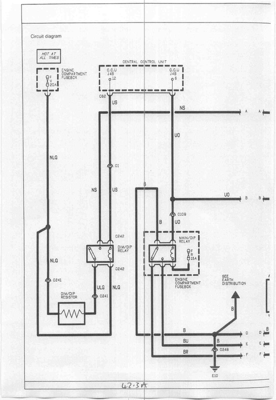  That's a much simpler system but still uses a simple wirewound resistor mounted on an aluminium heatsink bolted below the LH headlamp on the car that diagram pertains to. Many others were done in a similar way.
__________________
Cheers Dave Next Door to Top-Gun with a Honda CR-V & S Type Jag Volvo gone but not forgotten........
|
||
|
|
|
|
| Currently Active Users Viewing This Thread: 1 (0 members and 1 guests) | |
|
|


 Linear Mode

