
|
|||||||
| 850 / S70 & V70 '96-'99 / C70 '97-'05 General Forum for the 850 and P80-platform 70-series models |
 Information
|
|
How to make a Flash Code Reader, for DummiesViews : 16281 Replies : 32Users Viewing This Thread : |
 |
|
|
Thread Tools | Display Modes |
 Nov 9th, 2009, 16:46
|
#1 |
|
Phoenix from the ashes

Last Online: Apr 24th, 2024 01:05
Join Date: Jan 2006
Location: Finchingfield
|
It has recently been suggested to me that the flash code instructions previously posted do not work...
They Do... The reason in the majority of cases why you cannot get them to work is beacause you have not followed the instructions correctly..The balance is due to some wiring issues with your "obd2" socket and that it does not work on some 850R'.... Cars that give flash codes are: 850 and 70 10 Valve... 850 2.3 T5 (4.3 Motronic) 850 Jetronic (20V) Late 850 20V N/A and LPT running 4.4 Motronic, and all non 10V 70's do not produce flash codes. They are OBD2 complient.... Common error areas are highlighted.... First go to Maplin and buy a 12Volt LED, a normal bulb will not work...Part number is CJ63T in red £0.49 inc Buy a meter of Burglar Alarm cable, Part number is XR89W 4 core £0.59 Have some electrical tape, wire cutters and a paperclip handy...... 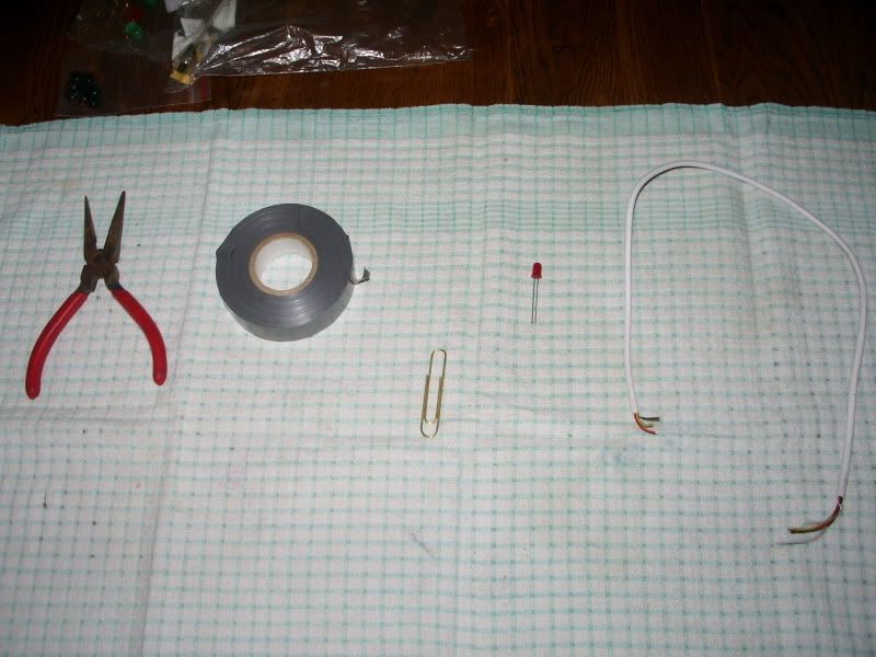 Establish that you are aware that the LED has one leg longer that the other..This indicates that the longer leg is the Positive (+) side and the shorter the Negative (-) side... You may want to test your led works, it should light off of a PP3 9V battery normally found in household fire detectors. Dont forget to replace it after.... 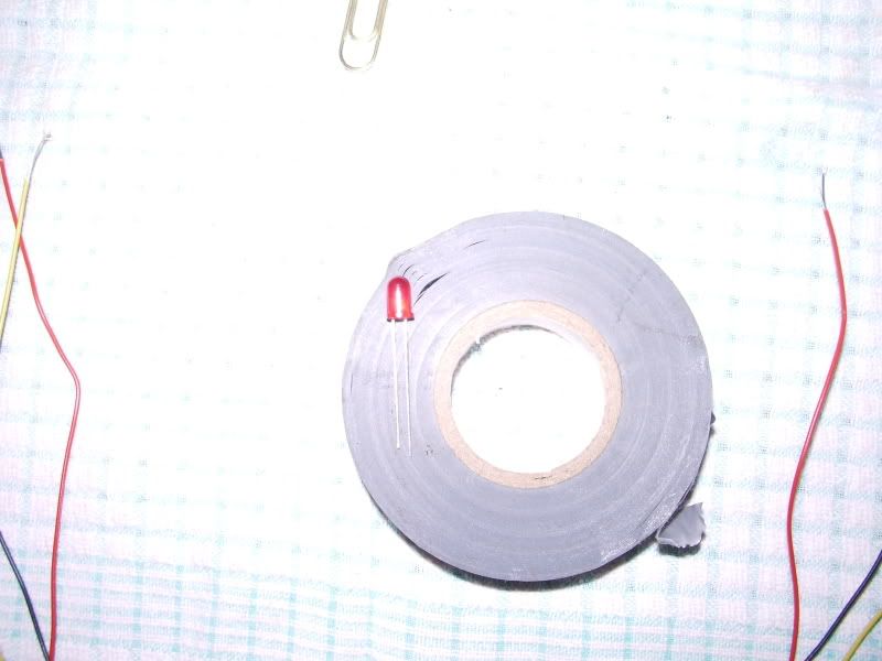 Cut the sheath of the Alarm wire and remove three of the lengths of wire. It may be useful to reduce the lengths to a shorter size...Strip 20mil of cover off each of the six ends....You will need to be able to identify which wire is which. I chose Red as + to LED, Black as - to LED and Yellow as my dipper... 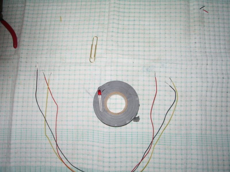 Using the Wire-cutters make three lengths of pin and attach one end of each to both your + (Red) and your dipper wire (Yellow)...Join the other end of your dipper wire (Yellow) to the end of your - wire (Black). Join this combination to another paperclip pin..You can now join the other end of the + (Red) wire to the longer leg of the Led and the other end of the - (Black) wire to the shorter leg of the Led.... 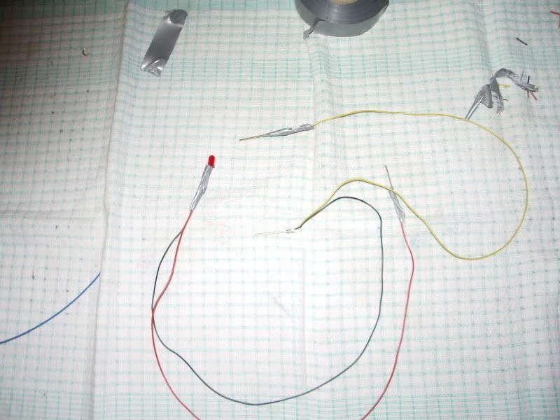 Emissions laws mean all modern cars have a OBD2 socket. The 850 is no exception and despite the fact it is very non-obd2 complient you have to use the socket to extract the Flash Codes... Flash Codes are not OBD2 codes... The socket is situated under the coin rack, next to the Cigar lighter... 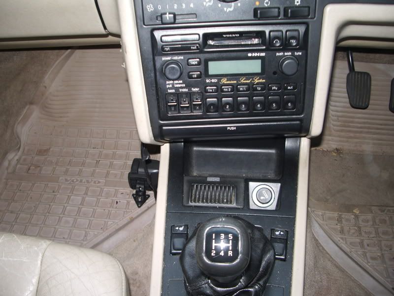 The socket is a 16 hole affair and the numbering is as follows... 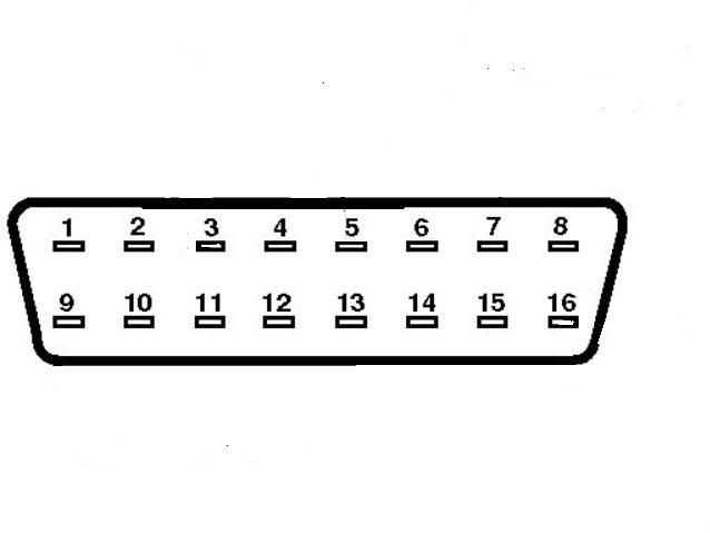 Insert the Red wire (+) paperclip into port 16... You can now check your LED is working by inserting the Black (-) paperclip into port 5. The LED should light. It should also light by replacing the Black (-) paperclip for the Yellow dipper into Port 5... It is best to have the LED in a place it is easy to see. It can be taped somewhere or the cassette opening on the radio provides a decent enough home... 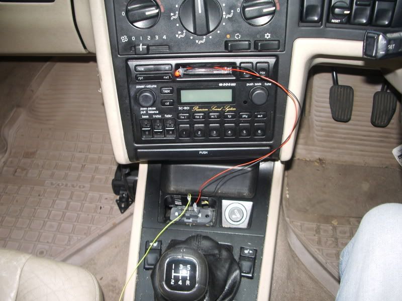 Remove all wires from port 5 Leaving the Red (+) paperclip in port 16, insert the Black (-) paperclip into port 3...You may see the LED light dimly...Turn the ignition to Pos 11 (with the warning lights on the dash, on)...If the LED was previously dimly illuminated then it will go out... Place your Yellow dipper wire into port 5 for 2 seconds and remove....During the time the dipper is in port 5 the light should illuminate... 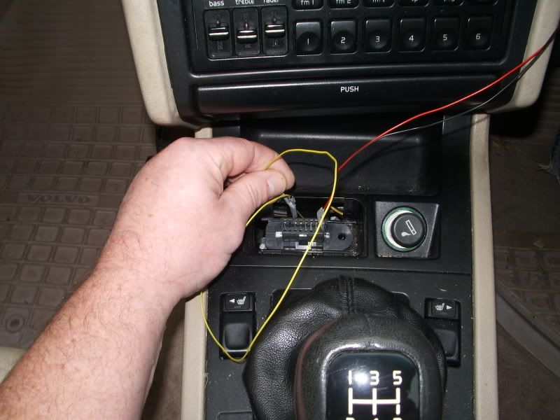 Count the flashes, taking the pauses into account... Jod
__________________
Dum Spiro Spero VOC 20419 Last edited by Jod T5; Nov 9th, 2009 at 16:57. |

|

|
| The Following 6 Users Say Thank You to Jod T5 For This Useful Post: |
|
Nov 9th, 2009, 20:26
|
#2 |
|
Trader
Last Online: Nov 29th, 2015 20:12
Join Date: Jun 2009
Location: Old Saybrook, CT
|
Nice write-up. This is handy when it is cold and/or raining and you don't want to have to pull the codes from under the hood.
__________________
FCP Euro Andrew Owendoff Communications Facilitator +1.877.634.0063 Get 10% off your order, use coupon code VOLVOFORUMUK : FCP Euro Official Car Parts Website <- Click |
|
|
|
|
Nov 9th, 2009, 22:36
|
#3 |
|
Master Member
Last Online: Apr 16th, 2024 13:36
Join Date: Dec 2006
Location: York
|
Excellent write up.
I struggled the first time until someone kindly pointed out that 12v led's have a longer leg for the +. Then it all worked! It was my duff electrical skills not the write up. BTW credit goes to the people who run the site and those who post as I got my response within an hour or so. Thanks Matt
__________________
 Get that kettle on! Get that kettle on!
|
|
|
|
| The Following User Says Thank You to Matthews 855 T5 For This Useful Post: |
|
Nov 10th, 2009, 15:50
|
#4 |
|
Senior Member
Last Online: Jun 21st, 2022 13:33
Join Date: Sep 2006
Location: Lausanne
|
Do you know if this method would also work for the Fenix 5.1 ECU mounted on a 1997 phase1 S/V40 with the 2.0 N/A petrol engine? That ECU is not OBD2 compliant but I've no idea whether it's a flash ECU (and I don't get much reply about that on the S40 forum...)
|
|
|
|
|
Nov 10th, 2009, 17:17
|
#5 |
|
VOC Member
Last Online: Apr 10th, 2017 16:55
Join Date: Jan 1970
Location: South Kent Coast
|
No it won't.
|
|
|
|
|
Nov 10th, 2009, 17:31
|
#6 |
|
Senior Member
Last Online: Jun 21st, 2022 13:33
Join Date: Sep 2006
Location: Lausanne
|
No way to build a similar thing for the Fenix 5.1? I've seen the Fenix 5.2 mounted on Volvo 850 10 valves N/A is also a flash ECU and ma be read with this design. Is the Fenix 5.1 that different?
On my Fenix 5.1, if I put my multimeter positive in pin 16 and negative in pin 5 I get a 12V signal. I also get a signal if I put the negative in pin 4 (doesn't go away when turning the key on II) but not in pin 3. Sounds close to the design on the first post though so I guess there should be some way to make it work with the Fenix 5.1, no? |
|
|
|
|
Nov 10th, 2009, 18:12
|
#7 |
|
VOC Member
Last Online: Apr 10th, 2017 16:55
Join Date: Jan 1970
Location: South Kent Coast
|
No, Fenix 5.1 does not produce flash codes, a scan tool is required for this ECU.
|
|
|
|
|
Nov 10th, 2009, 19:02
|
#8 |
|
Senior Member
Last Online: Jun 21st, 2022 13:33
Join Date: Sep 2006
Location: Lausanne
|
Oh OK, I guess I just got one of those ECU that are impossible to read from without the 10000$ Volvo tool
 Thanks anyway! |
|
|
|
|
Dec 28th, 2009, 10:35
|
#9 |
|
New Member
Last Online: Dec 31st, 2009 08:17
Join Date: Dec 2009
Location: Leicester
|
Great post but I'm having problems!
I've triple checked everything but can't get any flashes. The led illumates fine in 16(+) and 5 (-). It dimly lights in 16 & 3 but fails to go out when turning key to position II (definately II). The led then lights up fully for the 2 seconds whilst dipping in 5 but fails to do anything when removed. I have a 1995 850 2.5 auto (B5254S) but am unsure of the ignition system it uses. I have looked at the ECU but it doesn't appear to specify Jetronic or Motronic. The car doesn't have the underbonnet diagnostic unit. Any assistance would be appreciated |
|
|
|
|
Dec 28th, 2009, 15:30
|
#10 |
|
VOC Member
Last Online: Apr 10th, 2017 16:55
Join Date: Jan 1970
Location: South Kent Coast
|
I expect your 20 valve car has Motronic 4.4, which will need a scan tool, good news is that it's OBDII compliant so you can buy one quite cheaply.
Too make sure open the ECU box behind the RH headlamp and count the ECU's For a manual car, if there is one ECU then it will be Motronic 4.4 If there are two then it will have Jetronic. For an auto car add one ECU (for the transmission) to each of the above. |
|
|
|
| The Following User Says Thank You to Chris_Rogers For This Useful Post: |
|
| Currently Active Users Viewing This Thread: 1 (0 members and 1 guests) | |
|
|


 Linear Mode

