
|
|||||||
| PV, 120 (Amazon), 1800 General Forum for the Volvo PV, 120 and 1800 cars |
 Information
|
|
Aftermarket GaugesViews : 9797 Replies : 15Users Viewing This Thread : |
 |
|
|
Thread Tools | Display Modes |
 Jan 5th, 2010, 06:49
|
#1 |
|
Member

Last Online: Jun 29th, 2022 04:38
Join Date: Mar 2009
Location: Corvallis, Oregon USA
|
I installed a group of gauges in my estate a while back and would like to show how it was done for those interested. The gauges I chose are the Auto Meter Traditional Chrome series and I went with them because they match my interior superbly plus there's a nice selection of types in this series. Four 2-1/16" gauges were added: electrical water temp, electrical oil temp, electrical oil pressure, and mechanical vacuum.
A bit about my selection. The stock water temp gauge was broken when I bought the car so I had to get something for this. Recently due to bad leaks combined with my laziness I let the oil level get way too low ultimately resulting in me being stranded on the side of the highway as the fiber timing gear sheared a bunch of teeth off while doing 70 mph in the fast lane. Hence the oil pressure and temp gauges. The vacuum gauge is for assisting with engine tuning plus it's useful to get a visual baseline of what your engine does under different situations/loads. I read a lot of mechanical vs electrical threads and the bottom line is that electrical gauges are a bit easier to install and better for safety(no 50psi oil or fuel lines inside the cabin). Eventually I'll get a few gauges more when I do my custom dash but for now these are the bare essentials. Due to the size of the job replacing the timing gear and the oil sump seal I didn't take very many pics of the gauge stuff at the time of install. Tomorrow I'll take a bunch to show how I installed and wired the various sending units along with how/where I mounted the gauges. For now all I have is this, the gauge light bulb wiring harness. I had to get creative with the spade connectors to tap into the headlight switch in the space available. 
__________________
"Why is it that there's never enough time to do it right, but there's always enough time to do it again?" |

|

|
|
Jan 5th, 2010, 23:57
|
#2 |
|
foot in mouth specialist

Last Online: Sep 6th, 2016 22:55
Join Date: Sep 2009
Location: Dublin, Ireland
|
 i'm looking to add some gauges in myself, so i'm most interested to see where you put them and how you hooked them up! pics please, with loads of detail..  Ta, Gareth |
|
|
|
|
Jan 6th, 2010, 02:16
|
#3 |
|
Member
Last Online: Jun 29th, 2022 04:38
Join Date: Mar 2009
Location: Corvallis, Oregon USA
|
I'm going to break this into two parts due to the sheer amount of pics/info. I'll start off with the wiring at the back of the gauges which was probably the most tedious step of the whole install. Each electrical gauge needs a 12V+ switched connection, a sending unit connection, a connection that turns the inner light bulbs on with the headlights, a ground for the bulbs, and a gauge ground connection. I ended up building two separate wiring harnesses, one for the switched 12V+ & the gauge grounds and another for the light bulb 12V+ & their grounds.
First pic is where to tap into the ignition switch to get 12V+ when the key is on. I didn't have the fuse holder when I first built the wiring harness so I had to add it in later. This is very important to have in case one of the wires going to a sending unit ever shorts to the body in the engine bay somewhere. I'm using a 7.5 amp fuse in it since my CDP remote turn on signal wire is also spliced into this further down stream. The stud on the back of the switch is M4x0.7mm if I remember correctly in case you need more nuts.  This one shows where and how to splice into the headlight switch. I had to get creative here due to how many connections that need to come off of the single 1/4" male spade on the switch. It took me a little while to figure this one out and this pic is the best angle I could get to show the crazy part. Might have to take it off to show it better.  These two pics show how I simply used the wiper motor mount screws for the ground connections of the two harnesses as well as the one for my CDP.   This shows the general layout of the two wiring harnesses. You can also see where the sending unit wires come through the firewall. Luckily one of the rubber grommets supplied with the gauges fit this hole perfect.  Here's the engine side where the wires enter the cabin. I used a bit of split rubber vacuum hose to protect them from chaffing on the sharp edge of the heater blower housing. The color scheme I went with: Blue = water temp, Yellow = oil pressure, Brown = oil temp. 
__________________
"Why is it that there's never enough time to do it right, but there's always enough time to do it again?" |
|
|
|
| The Following User Says Thank You to dheming For This Useful Post: |
|
Jan 6th, 2010, 04:19
|
#4 |
|
Member
Last Online: Jun 29th, 2022 04:38
Join Date: Mar 2009
Location: Corvallis, Oregon USA
|
Round 2. Here's where I actually mounted the gauges using a pair of VDO dual mounting plates. For the most part they work okay here, my knees don't hit them, the shifter knob clears when in reverse, but when driving straight the wings of the steering wheel pretty much completely block the view of them. No big deal I just lean forward a bit. When I build my custom dash this won't be an issue any more. Don't mind the electrical tape on my instrument cluster, it keeps the chrome from reflecting off the windshield straight into my eyes.
 The center most gauge mount plate fit up flush no problem, but the outer plate required a spacer to keep it level due to the dash being slanted there. I simply cut a short piece of aluminum tube at a slight angle to match that of the dash. That was also the only hole I had to drill in the dash bottom. The other three I used various screws already present and drilled the mounting plates instead to be as non-invasive as possible.  Onto the sending units. For the water temp I went with an Auto Meter 2532 gauge. This comes with a few NPT adapters, but none of them fit the threads in the block. As luck would have it (this kinda stuff rarely happens let me tell you) if you remove the wire/sender from the stock threaded adapter the smooth inner bore is almost the exact size required to turn new 1/8"-27 NPT threads with a tap. Since it's a taper thread it still seals just fine even though the hole was a tiny bit too big. Couldn't have been easier.  For oil pressure I went with a 2522 gauge. Due to the massive size of the sending unit and proximity of the oil port on the block to the header a bit of creativity is required to mount it safely. Since my "low oil" idiot light doesn't work anyways I decided to keep the plumbing simple and just got rid of it's sender all together. The first part required is an Aeroquip FBM2511 1/8"-27 NPT male to #3AN male adapter. This allows you to connect a braided stainless brake line to the engine block to remotely mount the sending unit safely away from the heat of the header. I used an Earl's Performance 63011712ERL #3AN female straight to #3AN female 90° 12" long line for this. Finally you'll need an Aeroquip FBM2719 #3AN male to 1/8" NPT female adapter to connect the sender to the brake line. I just double zip-tied the sender to my speedo cable near the firewall for the time being.   For oil temp I went with a 2543 gauge which has a range of 140° to 300°. I was unsure how hot the oil got in my engine so when I was ordering all these parts I erred on the side of caution and got the higher range one. In practice my oil barely pushes 180° on long trips on the highway and during normal city driving the needle doesn't even move off its low rest. So I'd recommend the 2542 gauge instead which is 100° to 250°. I'll be replacing mine with this one soon. Now the bad news. The best place to mount the temp sender is in the sump and the best way to do that is use a weld in bung in the oil pan itself. Unfortunately it's a fairly big job to get the oil pan out, but I was already doing exactly that anyways since I had sheared my fiber timing gear and needed to clean the sump out. A much easier alternative is to mount it in a modified oil drain plug. The drawback to this method is that it will hang down quite a bit and could snag on something while driving. I used an Auto Meter 2260 1/8"-27 NPT weld in bung and TIG welded it into my oil pan.  I mounted the sender on the right hand side because I was worried about clearance with the starter motor but looking back I could have put it on the left side of the pan after all. I used some 1/4" clear tubing as armor to protect the wire on it's journey under the engine block.  You can see the clear tubing over the brown wire better here. BTW this pic also shows how I covered my main 4ga starter battery cable with heater hose. This is to protect it from general chaffing and more importantly will greatly reduce the chance of it directly shorting to the body in the case of a bad accident. I do this to all of my vehicles as cheap insurance.  Finally, the vacuum gauge is a 2484. This one is easy to hook up. Ideally this gauge would be directly connected to the intake manifold but I didn't want to take all that crap apart just to drill and tap a single hole. Instead I just tapped into the crankcase breather hose. The gauge comes with some vacuum line fittings but none of the would fit the 3/8" hose. I was going to go to a local car parts store to look for a 3/8" x 3/8" x 1/4" tee but decided not to because all their accessories are usually cheap Chinese plastic garbage. So I fabbed my own from 304 stainless tubing instead.   So in the end it's been really nice knowing what's going on at all times, especially the vacuum gauge since it's so dynamic. Even with just these four gauges the peace of mind while cruising on long trips is well worth all the cost and trouble installing them. I'm looking forward to getting a few more when the custom dash happens. Ahh, these kinds of threads take quite a while to put together. Time to grab a brew, Enjoy. 
__________________
"Why is it that there's never enough time to do it right, but there's always enough time to do it again?" Last edited by dheming; Jan 6th, 2010 at 04:27. |
|
|
|
| The Following 5 Users Say Thank You to dheming For This Useful Post: |
|
Jan 6th, 2010, 06:05
|
#5 |
|
New Member
Last Online: Aug 7th, 2012 17:48
Join Date: Dec 2009
Location: GA
|
between this and the brake upgrade thread, you certainly get my vote as someone who displays an attention to detail and willingness to document and share information! Seriously, you obviously took some time and effort to make this a reliable, clean installation and it comes across even in your photography and writeup.
|
|
|
|
| The Following 2 Users Say Thank You to red92s For This Useful Post: |
|
Jan 6th, 2010, 15:56
|
#6 |
|
Premier Member

Last Online: Apr 17th, 2024 12:54
Join Date: Jul 2008
Location: Co. Cork, Ireland.
|
Indeed, great thread with great work. Well done.
Hugh.
__________________
1970 Volvo Amazon 131 with a B20A and an M40. |
|
|
|
| The Following User Says Thank You to Alf ista For This Useful Post: |
|
Jan 6th, 2010, 20:47
|
#7 |
|
foot in mouth specialist
Last Online: Sep 6th, 2016 22:55
Join Date: Sep 2009
Location: Dublin, Ireland
|
good job dheming, looks very clean. it's great to see the job being done right. it's certainly given me food for thought when i start my build..
regards, Gareth |
|
|
|
| The Following User Says Thank You to redcar For This Useful Post: |
|
Jan 6th, 2010, 22:31
|
#8 |
|
Junior Member

|
Thanks, could'nt have been more timely ! Currently awaiting delivery of 5 gauges, so this is extremely useful!
|
|
|
|
| The Following User Says Thank You to dilip122S For This Useful Post: |
|
Jan 6th, 2010, 23:40
|
#9 |
|
Premier Member
Last Online: Apr 17th, 2024 12:54
Join Date: Jul 2008
Location: Co. Cork, Ireland.
|
I love analogue gauges. It makes a classic car. Sadly, the Amazon dosent have many. This is what I added recently:
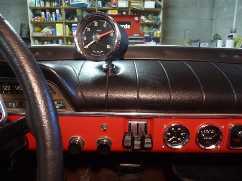 All these I got off ebay for good value. All Smiths gauges; the Rev counter is an impulse type that sits in line between the dizzy and the coil. The oil pressure gauge is mechanical, I used a splitter block so I could keep the warning light and used an armoured hose to the gauge. Luckily no leaks! The volt meter is an easy fit, just connected to the fuse board. For some reason my car seems never to have had an ashtray??? I have never seen a pic of another Amazon without one, so I dont understand why my one is different. A previous owner cut the holes for a temp gauge and an ignition cut off switch. I replaced the bust proper temp gauge with a new one from Brookhouse and then fitted these. I was considering fitting a vacuum gauge as well, especially since it looks to be an easy hook up. Not essential I know but hey neither is a lot of the things we do.
__________________
1970 Volvo Amazon 131 with a B20A and an M40. |
|
|
|
| The Following User Says Thank You to Alf ista For This Useful Post: |
|
Jan 7th, 2010, 04:54
|
#10 |
|
Member
Last Online: Jun 29th, 2022 04:38
Join Date: Mar 2009
Location: Corvallis, Oregon USA
|
Gentlemen,
Thank you for all the great comments. I figured quite a few people here would be interested in aftermarket gauges so I went all out with a fullsize picture build log. As such this thread may take quite a while to load for some so I apologize if that's the case. I don't like using thumbnails in these big posts since you still have to wait for each individual one to load, seems to take more time in the long run if you're planning to look at most of them anyway. Also thumbnail pics make it hard to read the description/comment while looking at the fullsize pic for reference since often times it covers up some of the text. Cheers, Derek Edit: I forgot to say those of you planning on installing gauges in their car in the future if you end up finding a better way to do any of the stuff above or if you just want to also share how/where you did the install please feel free to post it in this thread. This is by no means just "my" thread and it would be nice to have a few different viewpoints in one place.
__________________
"Why is it that there's never enough time to do it right, but there's always enough time to do it again?" Last edited by dheming; Jan 7th, 2010 at 05:01. |
|
|
|
| The Following 3 Users Say Thank You to dheming For This Useful Post: |
|
| Tags |
| auto meter, gauges, sending unit, speedometer, tachometer |
| Currently Active Users Viewing This Thread: 1 (0 members and 1 guests) | |
|
|


 Linear Mode

