
|
|||||||
| PV, 120 (Amazon), 1800 General Forum for the Volvo PV, 120 and 1800 cars |
 Information
|
|
My Supercharger ProjectViews : 29937 Replies : 104Users Viewing This Thread : |
 |
|
|
Thread Tools | Display Modes |
 Oct 17th, 2009, 08:09
|
#61 |
|
VOC Member
|
That all looks excellent quality.... can't wait to see it going in.
John
__________________
XX 
|

|

|
|
Oct 17th, 2009, 09:51
|
#62 |
|
Amazoniste

|
You'll be pleased to know that those front floors are indeed a good fit - my car has a set fitted, and they look correct.
Surprised to see that the rot had got as far as the gearbox crossmember! My chassis & outriggers had previously been bodged too, but had all that cut out when the new floors were also fitted earlier this year. A quick tip about an estate specific structural rot spot that is rarely mentioned - the rear chassis rails above the springs. I guess you'd have noticed if your car needed attention there, as you've had the axle off, so this is aimed more at other Amazon estate owners. With the axle, suspension & wheels in place, a seriously horrible mess can be hidden well out of sight of the MOT man.... Even with the wheels off, the full extent was still not visible on my car. Only once the springs were out, did I realise that I could put my finger through the spring cup and through the bottom of the chassis rail..... Fortunately new spring cups had just become available, and about 250mm of the bottom half of the chassis rails (pretty much centred on the spring cups) was replaced.
__________________
Paul - 1967 Amazon 222S B20 o/d Estate & 1961 A-H Sprite Mk2 948cc WANTED - For '67 Amazon estate - offside rear quarter, preferably new old stock. |
|
|
|
|
Oct 17th, 2009, 12:03
|
#63 |
|
Member

Last Online: Jun 11th, 2017 19:24
Join Date: Apr 2007
Location: Skipton
|
Yes indeed, my nearside chassis rail had a big hole hiding under the spring seat.
I didnt notice straight away as it had been covered with some sort of tape and underseal? Again the offside was perfect! |
|
|
|
|
Nov 29th, 2009, 17:06
|
#64 |
|
VOC Member
|
Is there any news on the metalwork?
Really looking forward to seeing it all solid again! John
__________________
XX
|
|
|
|
|
Nov 29th, 2009, 17:13
|
#65 |
|
Member
Last Online: Jun 11th, 2017 19:24
Join Date: Apr 2007
Location: Skipton
|
Hi John
Really slow progress at the moment. Its a real busy time for me at work. I need to get stuck in, i'm sick of the cart up on the ramps blocking the garage. By the way, what do you mean by "bridging filler" in your posts? Excuse my ignorance. |
|
|
|
|
Nov 29th, 2009, 17:25
|
#66 |
|
Trader Volvo in my veins

Last Online: Yesterday 23:53
Join Date: Dec 2004
Location: Anglesey
|
Bridging filler has fibre glass strand in it.It is used where filler thickness is a bit thicker than ideal(heavy build uparea. It issometimes abused and used to hold patches on or even build stuructual areas of the car such as pillars etc!
It is good stuff for sustom shaping etc where you have to build up a panel joint or similar where oridinary filler might crack. The joint does need to be fully weldedor it will crack due to teh flexing. |
|
|
|
|
Nov 29th, 2009, 17:35
|
#67 |
|
VOC Member
|
It's resin-based filler with glass fibres mixed into it. As the resin sets, the fibres give it far more strength that normal filler. It can cover a gap without cracking (unlike normal surface filler which should only be used on top of a continuous solid surface, with no gaps/cracks/holes).
I find that a fairly thin layer is best (say 2-4mm). At that thickness it is strong but still flexible. When applied thicker, it becomes more solid and brittle than the surrounding metal; if the metal flexes, it can potentially crack or pull away from the surface. But there has to be a lot of force to do that. I use it to seal and reinforce welded joints; it's an alternative to seam welding, the heat of which can create panel distortion problems. Bridging filler does not leave give a fine enough surface for painting, so it needs a layer of surface filler over the top. It's widely available, either at Halfords and the like, or at proper motor factors/trade suppliers. Various brands call it something slightly different, bridging filler, reinforced filler, fibreglass filler, but it's all very similar really. When you have time, put up some photos of the Amazon! Cheers John
__________________
XX
|
|
|
|
|
Feb 28th, 2010, 12:06
|
#68 |
|
Member
Last Online: Jun 11th, 2017 19:24
Join Date: Apr 2007
Location: Skipton
|
A bit more progress today. I concentrated on repairing the near side A post which had been poorly repaired before where it meets the cill at the bottom and also corroded at the top under the scuttle where the inner wing meets.
Poor earlier repair 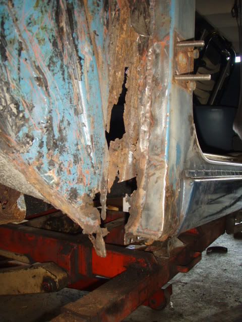 Corrosion at top of A post 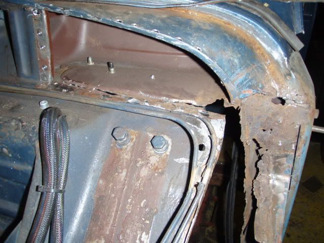 I had to remover spot welds and peel back the scuttle to cut out the rot at the top. I also had to cut out the complete leading edge of the A post. the inner face of the A post was also rotten where it met the bulkhead side so i began by cutting back the inner face and welding on an extension to give me something to weld the new side panel and the A post flange to. 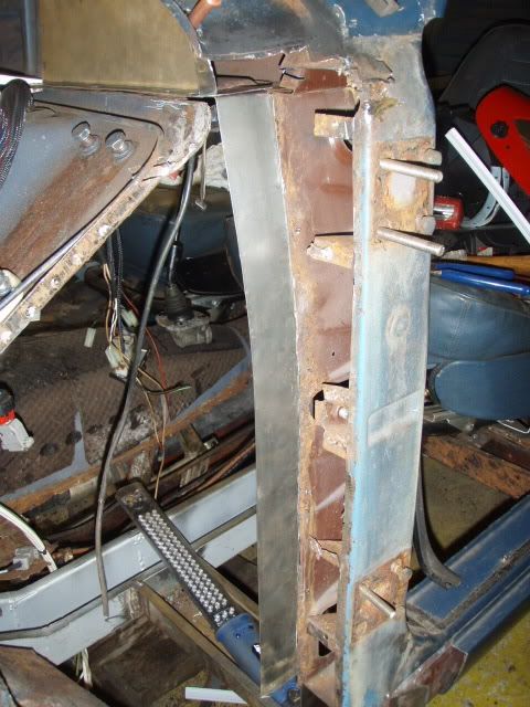 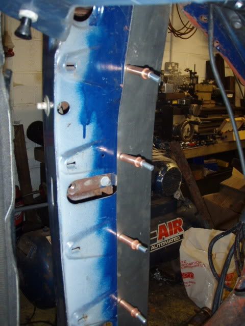 Next made a little curved patch for the top of the A post 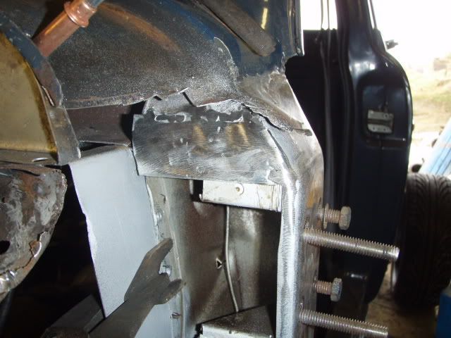 Then made a complete A post leading edge repair panel which closes off the inner cill and extends around the cill. 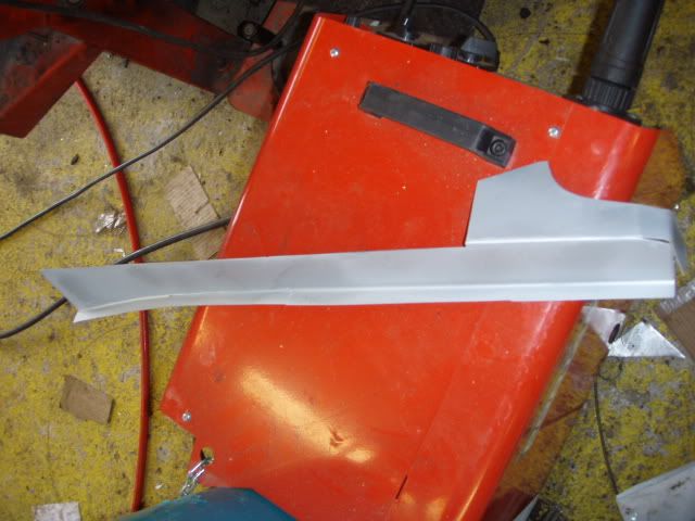 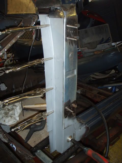 Thats all for today as i've just broken my angle grinder. Next job is to make a patch for the scuttle, weld in the side panel and then the inner wing. I'm still not sure how the inner wing repair panel is supposed to fit. Does the flange on the repair panel sit above or below the wheel arch? Any body know? Lots more pictures at http://s481.photobucket.com/albums/rr173/oilbeback/ |
|
|
|
|
Feb 28th, 2010, 22:03
|
#69 |
|
Junior Member

Last Online: Aug 24th, 2012 20:39
Join Date: Feb 2010
Location: bury
|
wow what an inspiring build! will be keeping an eye on this

|
|
|
|
|
Mar 21st, 2010, 15:43
|
#70 |
|
Member
Last Online: Jun 11th, 2017 19:24
Join Date: Apr 2007
Location: Skipton
|
Been modifying my fly wheel to take a 242mm diameter clutch from a Sierra Cosworth. This should easily handle the power of the supercharged engine plus there is a huge range of aftermarket clutches available for the Cosworth. I am also using a concentric clutch master cylinder to operate the clutch. This bolts onto the nose of the Type 9 gearbox with an adapter which i have yet to make.
The bigger clutch disc just fits inside the PCD of the original clutch cover mounting holes, and the Cosworth pressure plate is almost the same diameter as the flywheel. Because of the extra weight of the Ford clutch, i have lightened the fly wheel where i could safely do it. I have opened up the centre bore up to the diameter of the of the Cosworth plate, and have scalloped out three sections which are free on the periphery. I am taking the complete rotating assembly to be balanced at Impulse Developments in Rochdale. 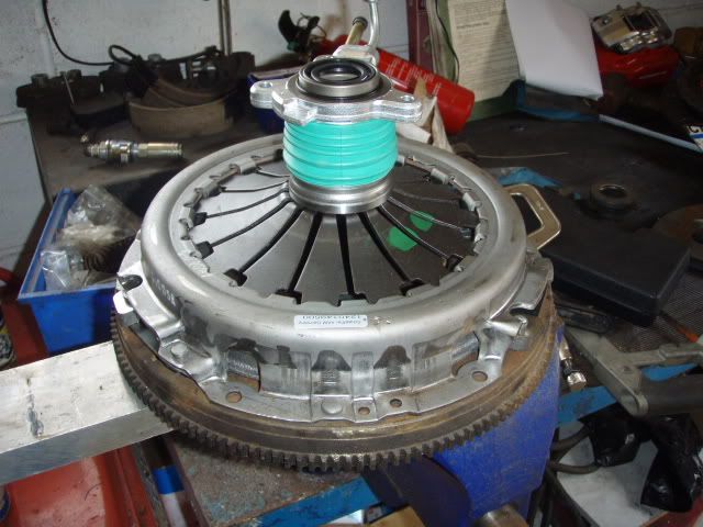 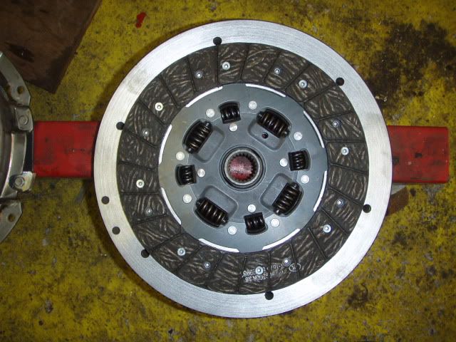 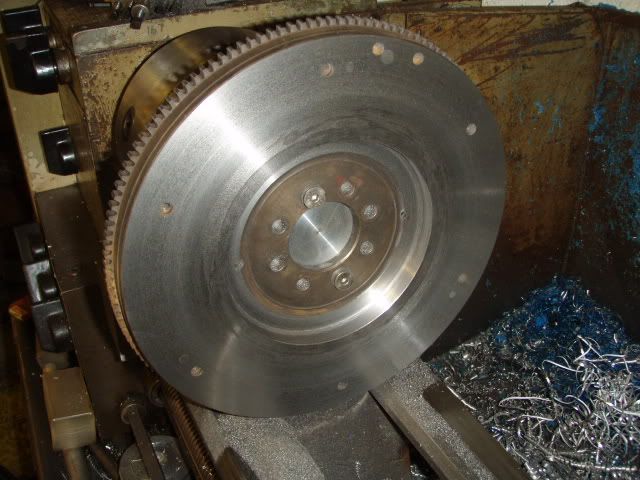 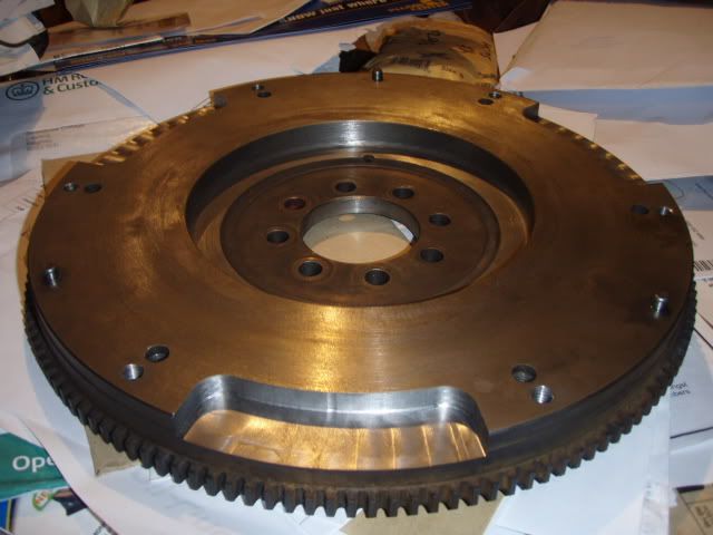
|
|
|
|
|
| Tags |
| big brakes, supercharger |
| Currently Active Users Viewing This Thread: 1 (0 members and 1 guests) | |
|
|


 Linear Mode

