Volvo Community Forum. The Forums of the Volvo Owners Club

Forum Rules Volvo Owners Club About VOC Volvo Gallery Links Volvo History Volvo Press
Go Back   Volvo Owners Club Forum > "Technical Topics" > 700/900 Series General
Register Members Cars Help Calendar Extra Stuff

Notices

700/900 Series General Forum for the Volvo 740, 760, 780, 940, 960 & S/V90 cars

Information
  • VOC Members: There is no login facility using your VOC membership number or the details from page 3 of the club magazine. You need to register in the normal way
  • AOL Customers: Make sure you check the 'Remember me' check box otherwise the AOL system may log you out during the session. This is a known issue with AOL.
  • AOL, Yahoo and Plus.net users. Forum owners such as us are finding that AOL, Yahoo and Plus.net are blocking a lot of email generated from forums. This may mean your registration activation and other emails will not get to you, or they may appear in your spam mailbox

Thread Informations

Fuel Gauge Fault - Fixed! Plus Ext. Temp/Time/Volts Display!

Views : 2982

Replies : 35

Users Viewing This Thread :  

Reply
 
Thread Tools Display Modes
Old Jan 16th, 2021, 14:18   #11
Tim1980
Junior Member
 

Last Online: Jun 15th, 2022 21:19
Join Date: Dec 2020
Location: Ruthin
Default

Quote:
Originally Posted by Laird Scooby View Post
We all know the fuel gauges on the 7/9xx are prone to not working or only working intermittently. Since i got my current 760, the gauge has had the work ethics of a 1970s coal miner. My previous 740 was the same and i designed and built an LED bargraph gauge for that :


Having done various tests on my 760, i had come to the conclusion that wasn't an option. The fault appeared to lie somewhere between the gauge and the car wiring - that left the PCB on the back of the instrument cluster.


Looking at that, at first glance it looks like an explosion in a spaghetti factory but delving in, i made some sense out of it. The 3-pole connector on the PCB centre-top is +ve, -ve and speedo signal. This also provides the +ve feed for the rest of the cluster including warning lamps, speedo and temp gauge.
You'd think if the fuel gauge was dropping out, the rest would as well? In several cases you'd be right but have a look at these pics :


This is a close up of 3 out of the 4 solder pad connections near the PCB fuse to the left. at the top. They weren't great and using the continuity tester on my multimeter, i could switch the buzzer in it on and off by wiggling the PCB around the fuse area.
As such, these 4 pads were my first port of call for repair. Smeared a little soldering flux on them, heated them up with the iron and removed the old solder with a solder-sucker.
A little more soldering flux then resoldered with some new real solder - that's most of the problem, the original isn't proper solder!

Thanks to the EU, back in the mid-late 80s, leaded solder in the workplace was outlawed by the EU - the lead-free replacement does NOT stand the test of time!

I also added an aftermarket clock/internal & external temperature display/voltmeter, picking up the +ve feed from the back of the fuel gauge and the -ve from the electronic rheostat for the panel lighting on the back of the cluster. I need to make a proper bracket for the display module and find better places for the temperature sensors (they can give some strange readings at present due to their locations! ) but here's the module fitted to the cluster :


After repairing theose 4 solder pads, i was hopeful i'd cracked it, especially as i'd been able to make at least one of them act as a switch!

However, testing in the car proved me wrong, although for the first 10 minutes i thought i'd done it. Then the fuel gauge dropped like a stone and the display disappeared from the module.
This was incredibly useful in diagnostic terms. It left two more solder pad connections that were potentially the source of the fault.


The one just underneath the indicator tell-tale and the one the other end of the dotted line from it. These two in fact :


Left hand pad, near the tell-tale. 'orrible, ain't it?


Pad t'other end of the dotted line, not much better!


After removing old solder and applying new!

Refitted the cluster yesterday morning and had to go shopping which gave it a reasonably long test - all good thankfully, despite doing everything i could to make it fault! I'd previously worked out that if the gauge worked from cold, once i got some warmth in the car, it would die. Conversely if it didn't work from cold, by getting some warmth into the car, i could make it work - turning the heat down after this would cause it to drop out again. None of these things effect it now thankfully!

Also a short vid of the module in operation :

https://youtu.be/qe5B09I4BYk

One of the temperature sensors is tucked onto a clip on the back of the instrument cluster so gets all the heat from the footwell and any heat from the cluster, the other goes into the engine bay then onto the plenum cover over the wiper mech under the bonnet. After the car has been sat, heat from the engine bay warms this area, it drops off fairly quickly once under way and is obviously accurate from a cold start.
Ideally i'd like a longer lead on both sensors, the internal one could go in a more "real world" place like behind the A-pillar trim and the external one could be sited either further forward just behind the radiator grille or in a wheelarch or similar. I'll look into a longer sensor for the external one then use the present external one as the internal one in a better place - all stuff for the future and if i take the positions of the current sensors into consideration and allow time for them to settle, i get sensible readings.

Ultimately i'll also fit some remote buttons for the setting of the clock but for now i'm happy that it's in there and providing some useful information!

https://www.ebay.co.uk/itm/Multifunc...1/392348762865

That's the new module, available in a choice of display colours (red, blue and green) from various sellers. Mine had to come from China on a slow boat so i've been waiting a while to fit it.

Hopefully that gives some insight into the dodgy fuel gauges and maybe other problems with the clusters! This one is a Yazaki so is likely to apply to most 940s/960s as well as facelift 7xx, the earlier VDO clusters have their own strange problems and because many of them were made before the EU Directive on solder, are less likely to suffer this particular problem.


Mine looks very different, more German and less Japanese than yours! And I can't see any solder joints like yours to go wrong...

I'm going to dismantle further, but I'm guessing mine is not the Japanese unit?

Last edited by Tim1980; Jan 16th, 2021 at 14:22.
Tim1980 is offline   Reply With Quote
Old Jan 16th, 2021, 14:31   #12
bob12
bob12
 

Last Online: Yesterday 18:44
Join Date: Aug 2006
Location: Woking
Default

That's a VDO not a Yazaki cluster that's why it looks different. Be very careful with your soldering iron near the blue plastic as it doesn't react well to heat! However you are OK soldering an individual instrument's pcb once removed from the cluster.

Bob
bob12 is offline   Reply With Quote
The Following 2 Users Say Thank You to bob12 For This Useful Post:
Old Jan 16th, 2021, 14:36   #13
Tim1980
Junior Member
 

Last Online: Jun 15th, 2022 21:19
Join Date: Dec 2020
Location: Ruthin
Default

[

Quote:
Originally Posted by bob12 View Post
That's a VDO not a Yazaki cluster that's why it looks different. Be very careful with your soldering iron near the blue plastic as it doesn't react well to heat! However you are OK soldering an individual instrument's pcb once removed from the cluster.

Bob
Cheers.
I'm having problems getting the instruments off the circuit part now, I've unscrewed all the screws I can see, but it won't come. I don't want to pull it too hard in case I break something!
Tim1980 is offline   Reply With Quote
The Following User Says Thank You to Tim1980 For This Useful Post:
Old Jan 16th, 2021, 14:36   #14
Laird Scooby
Premier Member
 
Laird Scooby's Avatar
 

Last Online: Today 01:27
Join Date: May 2012
Location: Lakenheath
Default

Quote:
Originally Posted by Tim1980 View Post


Mine looks very different, more German and less Japanese than yours! And I can't see any solder joints like yours to go wrong...
Ja Tim, dein ist ein VDO von Deutschland!

Yes Tim, yours is a VDO from Germany - that's why it looks different! The pics showing the cluster with the LED fuel gauge are of a VDO, the rest are Yazaki.

Don't ask me for a Japanese version of that though!

The VDO uses crimped and/or welded joints instead of soldered joints. If it's a welded joint that has failed, you're left with few if any options to repair it, sometimes over-soldering will work but not always.

Some things will cross over from the Yazaki to the VDO in what i've put in this thread, however most of it won't. If your fuel gauge isn't working and you have a VDO, chances are it's the gauge itself.
__________________
Cheers
Dave

Next Door to Top-Gun with a Honda CR-V & S Type Jag Volvo gone but not forgotten........
Laird Scooby is offline   Reply With Quote
The Following 2 Users Say Thank You to Laird Scooby For This Useful Post:
Old Jan 16th, 2021, 14:39   #15
Tim1980
Junior Member
 

Last Online: Jun 15th, 2022 21:19
Join Date: Dec 2020
Location: Ruthin
Default

Ok thanks Dave.

So the speed sender and the fuel sender might be the cause?

That's for another day if so!
Tim1980 is offline   Reply With Quote
Old Jan 16th, 2021, 14:47   #16
bob12
bob12
 

Last Online: Yesterday 18:44
Join Date: Aug 2006
Location: Woking
Default

For some info on the VDO have a look at Dave Barton's website at: https://www.prancingmoose.com/740-odometer-repair.html

Bob
bob12 is offline   Reply With Quote
The Following User Says Thank You to bob12 For This Useful Post:
Old Jan 16th, 2021, 14:48   #17
Laird Scooby
Premier Member
 
Laird Scooby's Avatar
 

Last Online: Today 01:27
Join Date: May 2012
Location: Lakenheath
Default

Quote:
Originally Posted by Tim1980 View Post
Ok thanks Dave.

So the speed sender and the fuel sender might be the cause?

That's for another day if so!
Quote:
Originally Posted by Laird Scooby View Post
If your fuel gauge isn't working and you have a VDO, chances are it's the gauge itself.
Set your multimeter to resistance Tim and check the resistance between the +ve terminal on the speedo connection and the +ve terminal on the fuel gauge. Should be zero or as near as.
Then check the -ve connections from the speedo to the fuel gauge.

If all is well then almost certainly the gauge. You can check this with a 270 Ohm resistor by disconnecting the 3-pin multiplug in the rear cubby hole next to where the spare wheel lives. Go on the car side of things, not the tank side and connect one end of the resistor to earth, the other to the third wire in the plug - there is a pink, a brown and a third colour i don't recall at present - make sure you ONLY connect to that third wire!!!

Switch the ignition on and observe the fuel gauge, should be between 3/4 and full if it's working. I doubt it will move though to be honest.

Is your speedo not working either?
__________________
Cheers
Dave

Next Door to Top-Gun with a Honda CR-V & S Type Jag Volvo gone but not forgotten........

Last edited by Laird Scooby; Jan 16th, 2021 at 14:49. Reason: Speedo
Laird Scooby is offline   Reply With Quote
The Following 2 Users Say Thank You to Laird Scooby For This Useful Post:
Old Jan 16th, 2021, 15:11   #18
bob12
bob12
 

Last Online: Yesterday 18:44
Join Date: Aug 2006
Location: Woking
Default

If you seem to be having a problem removing the speedo after undoing the 4 holding screws it looks to me as though you have a speedo with 5 thin pin connectors off its pcb rather than the older style with tags off the pcb as the large white plastic moulding to the side of the speedo on the back board appears to be empty. The pins tend to hold the speedo on to the female connector attached to the blue plastic.

When you put it back make sure you don't bend the pins and ensure they insert correctly into their female counterpart rather than slipping to one side.

The speedo is a tight fit anyway but just pull it out and it will separate as there is nothing more holding it in position..

Bob
bob12 is offline   Reply With Quote
The Following 2 Users Say Thank You to bob12 For This Useful Post:
Old Jan 16th, 2021, 15:43   #19
Laird Scooby
Premier Member
 
Laird Scooby's Avatar
 

Last Online: Today 01:27
Join Date: May 2012
Location: Lakenheath
Default


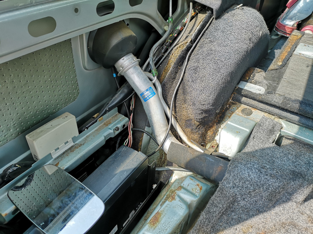
Just left of centre you can see the pink and brown wires, next to them is a mainly white one, if memory serves this has a green trace along it, that's the one you need to test the gauge.
__________________
Cheers
Dave

Next Door to Top-Gun with a Honda CR-V & S Type Jag Volvo gone but not forgotten........
Laird Scooby is offline   Reply With Quote
The Following 2 Users Say Thank You to Laird Scooby For This Useful Post:
Old Jan 16th, 2021, 18:32   #20
Tim1980
Junior Member
 

Last Online: Jun 15th, 2022 21:19
Join Date: Dec 2020
Location: Ruthin
Default

Quote:
Originally Posted by Laird Scooby View Post

Is your speedo not working either?
No, speedo, milage counter and fuel guage.
Speedo has intermittently worked but mostly doesn't. Fuel guage is busy chatting nonsense all the time, perhaps some of its random readings might be correct. Odometer and trip counter just don't do anything.
Tim1980 is offline   Reply With Quote
The Following User Says Thank You to Tim1980 For This Useful Post:
Reply


Currently Active Users Viewing This Thread: 1 (0 members and 1 guests)
 

Posting Rules
You may not post new threads
You may not post replies
You may not post attachments
You may not edit your posts

BB code is On
Smilies are On
[IMG] code is On
HTML code is Off

Forum Jump


All times are GMT +1. The time now is 06:41.


Powered by vBulletin
Copyright ©2000 - 2024, Jelsoft Enterprises Ltd.