
|
|||||||
| S80 '98-'06 / S60 '00-'09 / V70 & XC70 '00-'07 General Forum for the P2-platform S60 / V70 / XC70 / S80 models |
 Information
|
|
BT Hands Free kit S60 installViews : 2320 Replies : 11Users Viewing This Thread : |
 |
|
|
Thread Tools | Display Modes |
|
|
 Aug 4th, 2013, 00:15
|
#1 |
|
VOC Member

Last Online: Nov 6th, 2016 10:18
Join Date: May 2009
Location: Blackpool UK
|
Fitting a Bluetooth capable handsfree kit to an S60 2004 with remote (under the front seat) Volvo Amplifier which also supports music streaming via Bluetooth and a whole plethora of other inputs for various hardware you might want to use in the car for audio:
BT Handsfree for the phone BT Music Streaming BT Track control/ Pause 1/8" Socket for mp3 player support RCA Phono input iPhone/ iPAD/ iPOD interface with charging capability Simple to use controller Head up OLED Display Not an easy install as I decided to wire this without using adapter cables, I have previously tried to use a SOT-1000 adapter box to work with a Volvo headunit and remote amp with little success as the supplied leads were woefully inadequate with supplied wires simply falling out of the plugs and the wiring diagram supplied with the SOT-1000 may as well have been in a different language so a different approach was needed this time around. This starts with the disconnection of the battery negative lead, if you don't do this and decide to follow the write up you will probably trigger an SRS airbag fault, so the first step is to remove the four bolts securing the drivers seat in to the car (UK) passenger front seat if you are on the other side of the "Pond" With the seat unbolted and the battery disconnected you can rock the seat back to gain access to the seats electrical connections, first to go are the two grey plugs that simply disconnect with a press of the raised tab to release the plug: 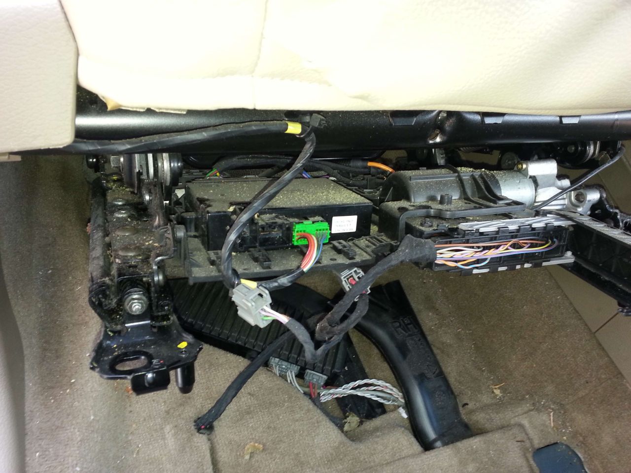 Next is the larger connector which releases as you hinge the cover portion away from the seat, once the cover is fully open the plug should simply pull away from the seat: 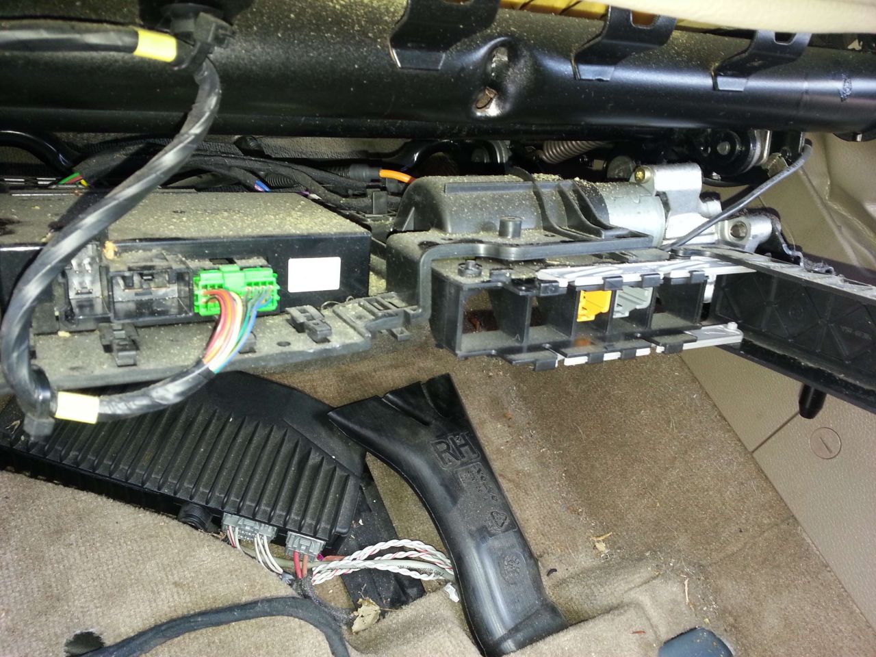 Put the seats electrical connections and associated loom in to the front footwell so it is well out of the way prior to extracting the seat:  The outboard seat trim with the switch pack in has to come off, lift this up at the forward edge then slide the entire panel aft for it to release from the structure of the seat: 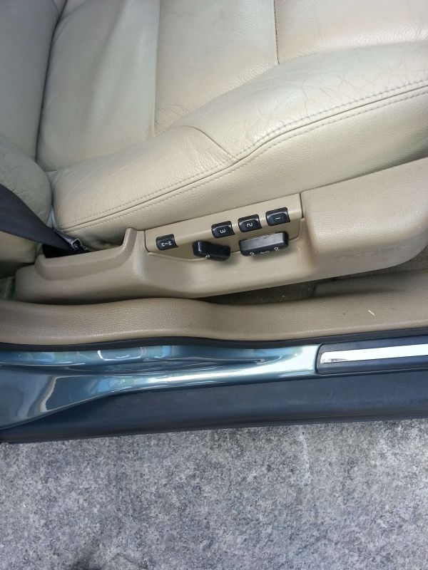 Two reasons for releasing the seat switch pack panel: 1/ It makes it easier to remove the seat as the presented width of the seat is reduced 2/ It affords access to the seatbelt quick release coupling to disconnect the seatbelt from the seat 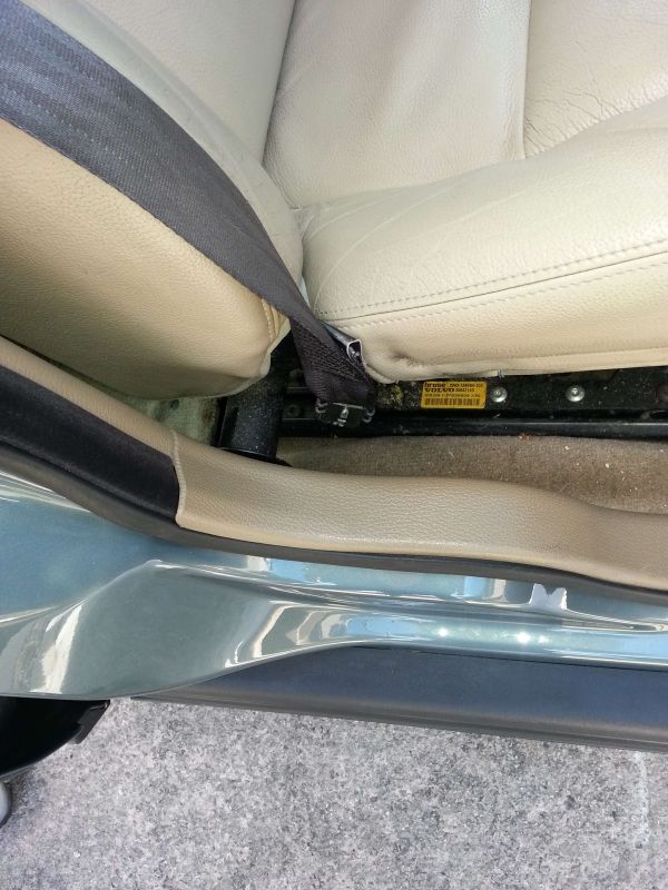 The seatbelt quick release coupling has three bright metal components in a row down the centre of the coupling, the middle one is the release pin, depress this with a screwdriver whilst pulling the seatbelt away from the seat: 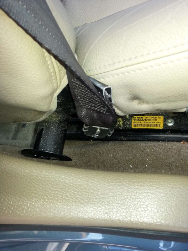 Once the seatbelt is released you should end up with something like this, at this point the seat can be removed from the vehicle: 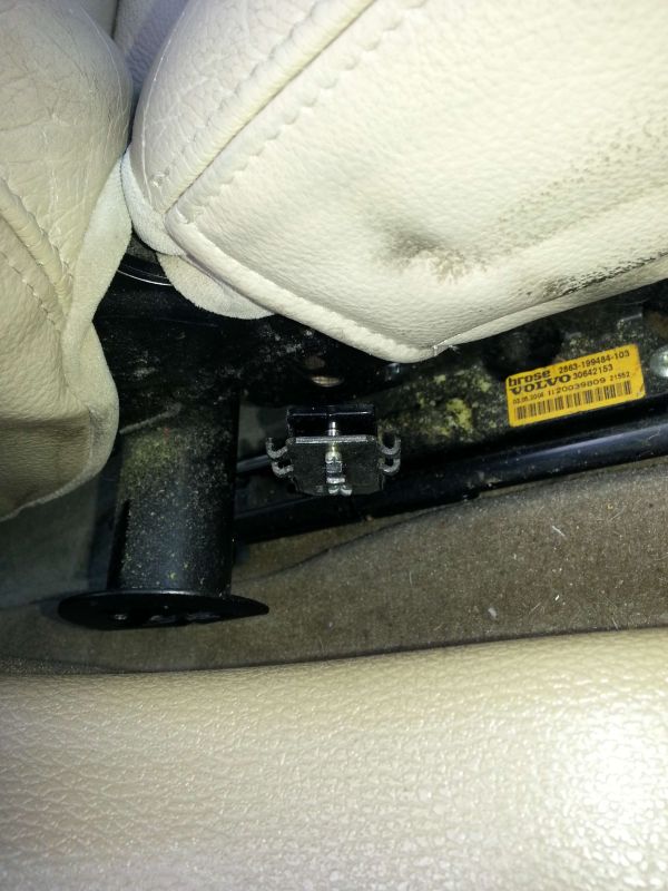 With the seat out of the car attention can turn to the under seat amplifier, but to increase access the air delivery pipe to the rear under floor area should be removed (Now you see it)  Now you don't, the air pipe simply pulls to the rear of the car to release it from the fixed portion of pipe: 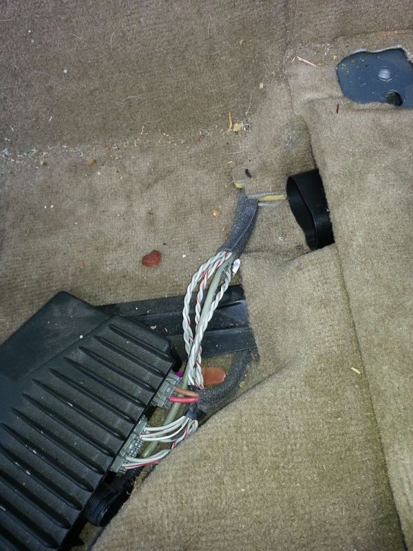 Pull the carpet back to access the 10MM head bolt securing the forward amplifier attachment bolt and remove it: 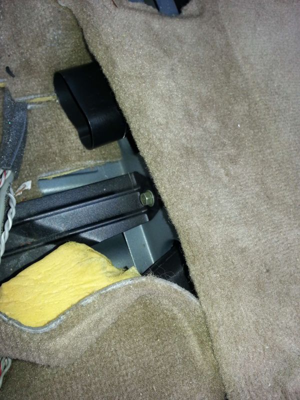 Pull the carpet back to access to the 10MM head bolt securing the rear amplifier attachment bolt and remove it: 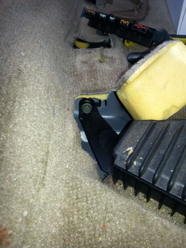 With the amplifier no longer attached to the car you can move it to disconnect the electrical plugs: 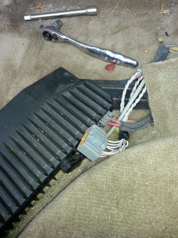 Next attention turned to the additional parts of the handsfree kit such as the microphone, I decided to run the cable under the carpet then up the "B" pillar of the car, along the top edge of the door to it's chosen location where the "A" pillar meets the roof, nice easy way to do this which avoids disturbing too much trim is to pull the rubber door seal away which gives access to a small gap large enough to house a thin microphone wire: 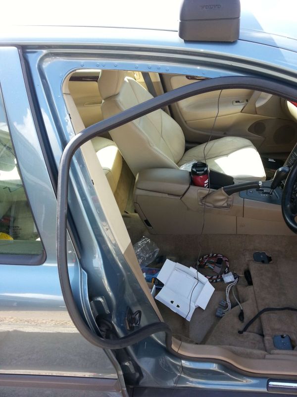 The microphone attached to the top of the "A" Pillar trim panel with the wire fed through to exit through the gap where the door seal usually resides: 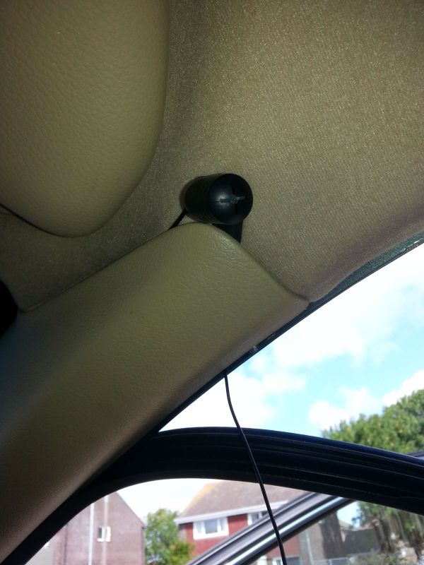 Simply insert a few inches of microphone cable in to the gap between the roof and the headlining as you re-attach the rubber door seal which traps the cable in the small void, work all the way around the door frame to the base of the "B" Pillar where the cable goes under the plastic trim, under the carpet to a location near the Volvo amplifier, the supplied cable is more than adequate in length: 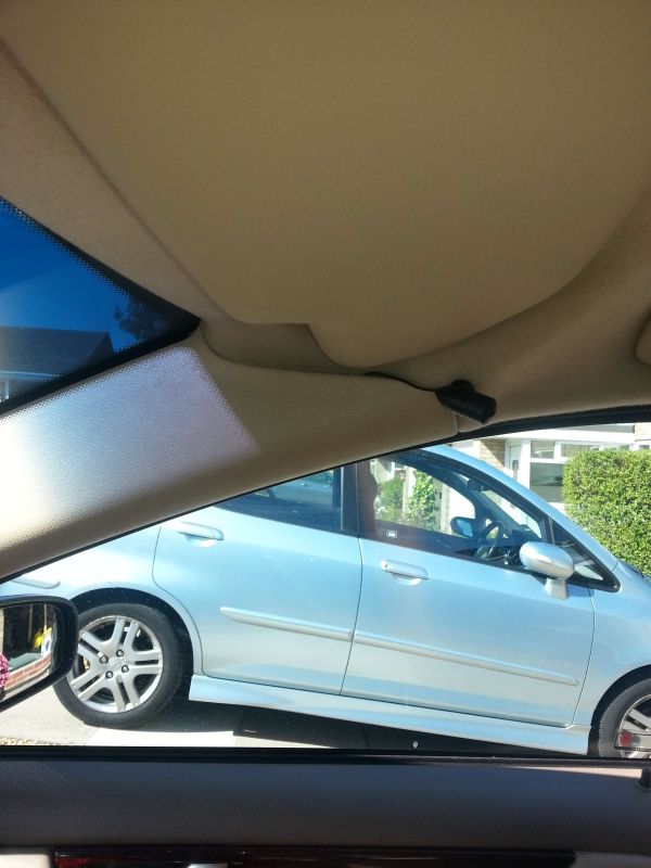 Next is to gain access to the wiring at the rear of the stereo, for this specific install I was adding a powered Brodit/ Pro-Clip phone holder and three way 12V charger outlet with USB sockets as well as routing power to a Road Angel camera detector which needed access to the rear of the stereo, in addition the car has a centre speaker which we needed to disable when the Bluetooth kit was in operation. So with the gear shift trim and pen holder trim removed along with the two T20 bolts that secure the aircon panel in to position this was wrestled away from the car. Pull it out to the rear of the car at the base of the panel then pull down, eventually after some time it will release from the two sprung steel attachments retaining the upper portion in to position: 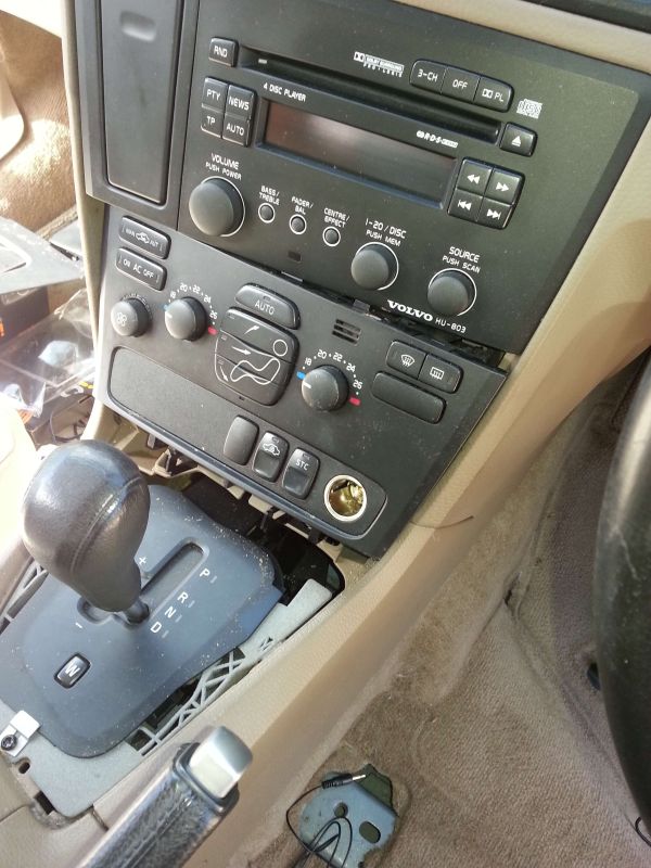 Disconnect the Aux 12V socket and two green plugs from the rear of the climatic control panel which reveals two more T20 bolts that secure the Volvo headunit in place, once these are removed the headunit and cup-holder/ phone data panel can be lowered, unplugged and removed from the dash: 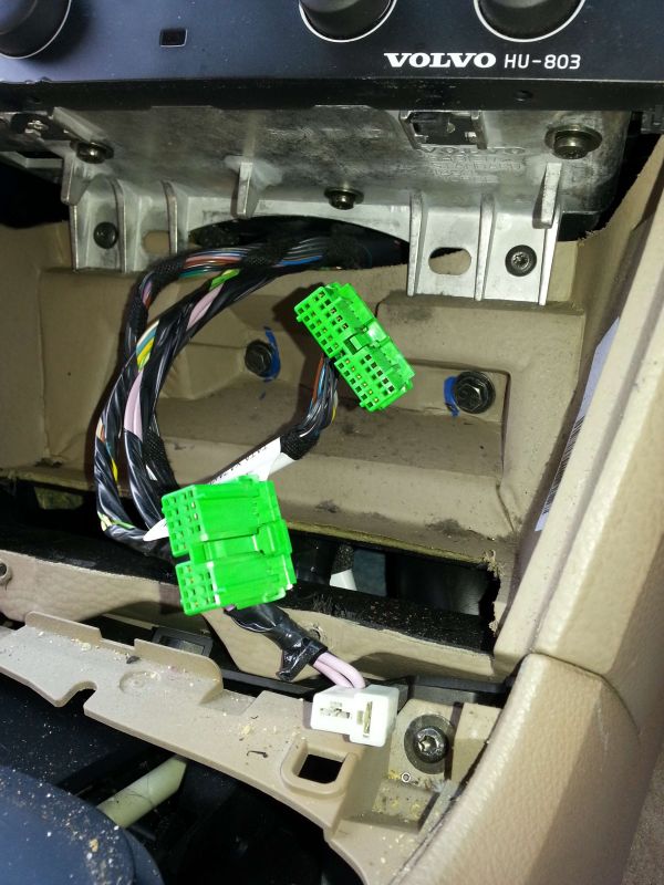 The side trim from the centre console is removed to increase access to run a few wires between the aperture the headunit and climatic control panel reside in and the area under the front seat adjacent to the amplifier: 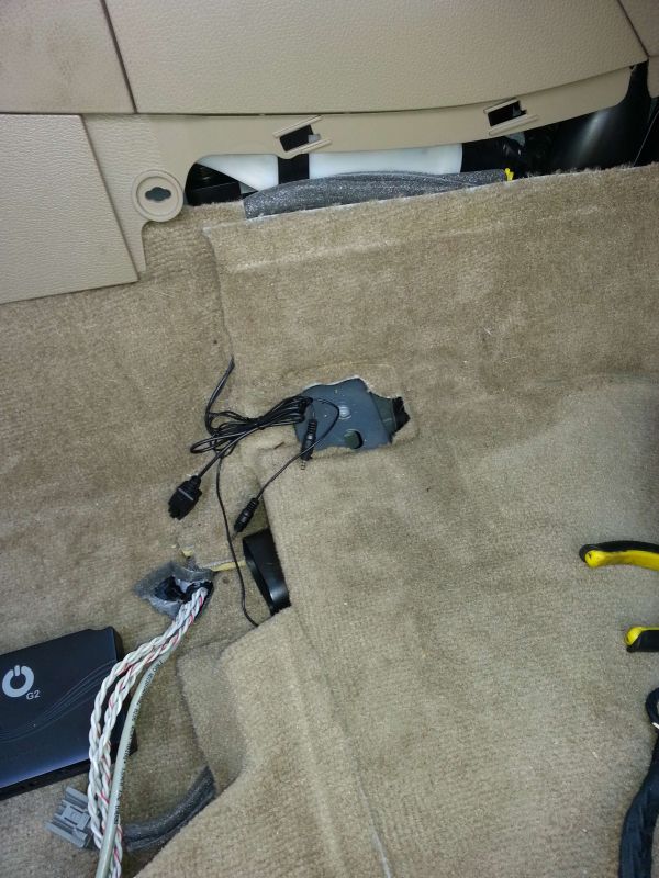 Checking for adequate cable length for the iO-Play_2 head up OLED display unit, excess cable was left under the front seat coiled up and restrained once the required length was established, also the hand controller cable was routed through the dash leaving it residing next to the gear selector lever for later: 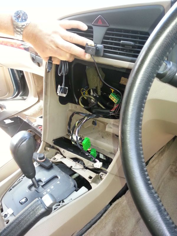 At this point the other "Wired" inputs to the iO-Play_2 kit were routed under the carpet and up in to the rear portion of the centre console, this included the iPhone/ iPOD cable, a 1/8" or 3,5MM jack socket for mp3 players and a pair of RCA Phono sockets should they be needed for anything else. With the ever increasing "puddle" of cables the next part is probably the most difficult, hooking up the wiring between the Volvo amplifier cables and the I/O cable harness supplied with the Bluetooth kit, to avoid excess cable I decided to cut the cables down to something more suitable for the installation, as you can see the supplied harness is quite long and would end up tangled up in someone's feet if you tried to hide that lot: 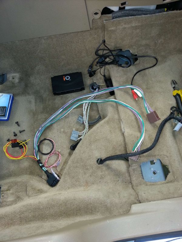 About 4" away from the Volvo amplifier connector the speaker feeder cable was cut, only cut one twisted pair at a time as the Volvo wires are very similar in colour, the wires to the Bluetooth kit were reduced in length and spliced to the cut wires: 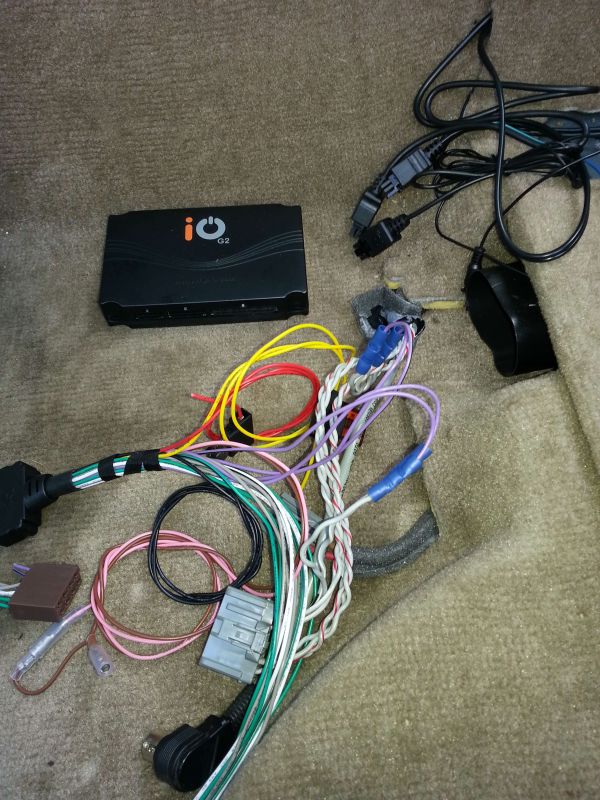 This cutting of a pair of twisted cables from the Volvo amp and splicing to the Bluetooth kit continues until all 16 connections have been made: 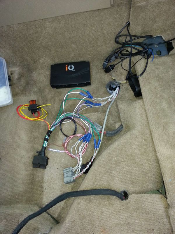 The pile of scrap cable and connectors removed from the Bluetooth kit: 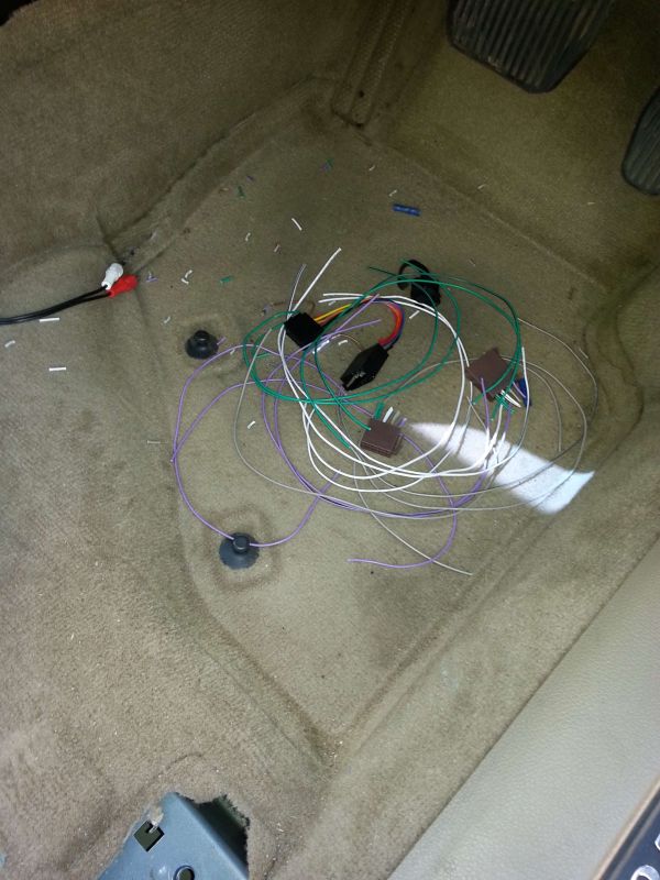 To earth the Bluetooth kit I decided to put a ring tong tag on the black ground cable then secure it to the frame of the car through the forward Volvo amplifier attachment bolt, saves running more wires through the car: 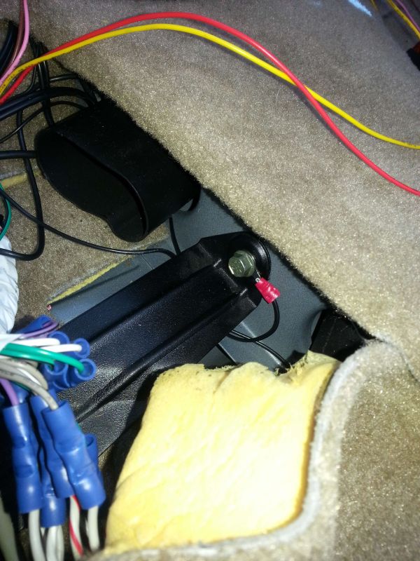 At this point all the wires for the speakers are connected, the remaining wires needed to be extended to get them to where required: Red 12V IGN Sw Yell 12 Batt Brown AND Pink Mute (this cable supplies a 0V signal when the Bluetooth kit is in use and can be used in conjunction with a cheap automotive accessory relay to disable the Volvo centre speaker) 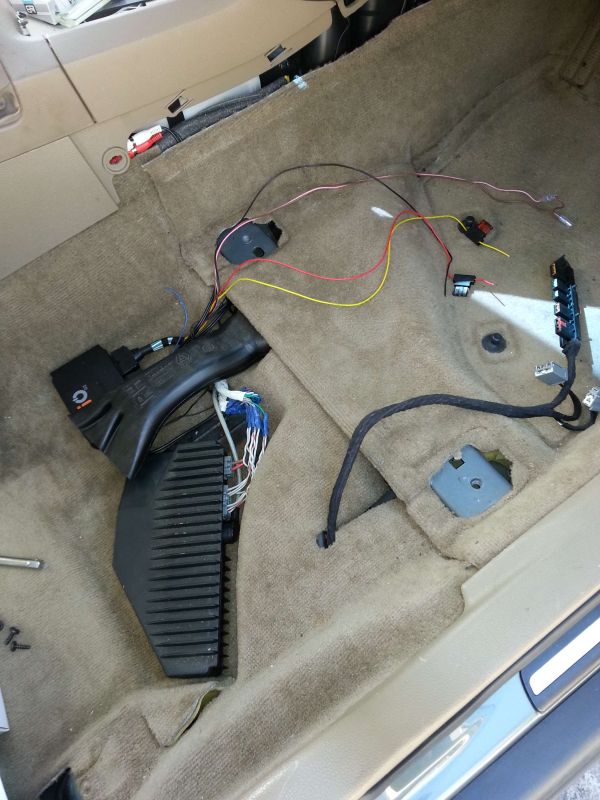 The accessory relay is used to break the grey/ red wire from the head unit feeding the centre speaker, the coil of the relay is fed with a switched 0V signal from the Bluetooth kit, the other side of the coil is connected to an ignition switch controlled 12V+ supply: 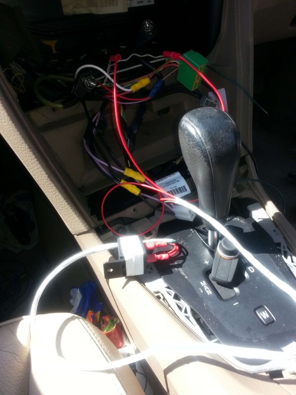 Get the Dremel out with a diamond coated slitting disk and cut a small slot in the trim for the OLED display wires to exit from, the head unit will hide this this small cut once it is back in place: 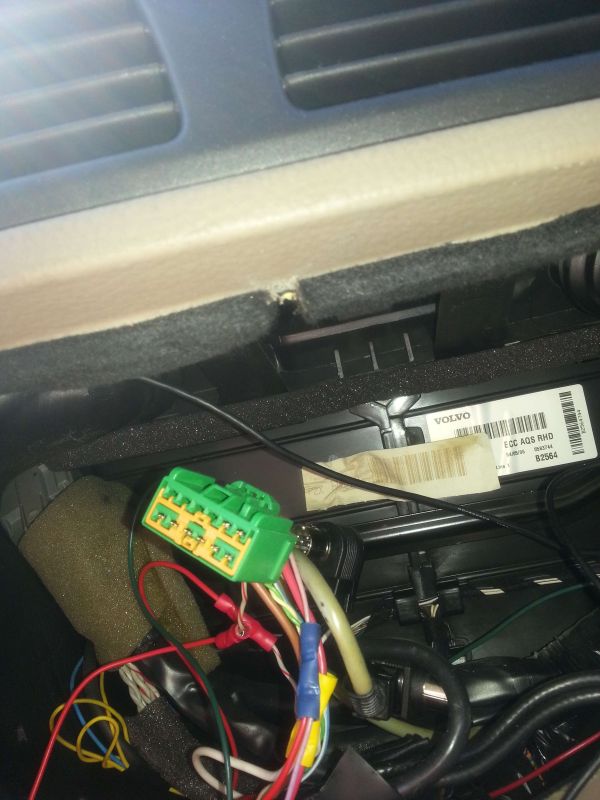 A corresponding small cut in the top of the head unit for the OLED display unit cable to exit, again made with the dremel, without this cable exit the OLED display cable would be severed when the head unit was secured back in place due to the sharp edges and close fit of the trim: 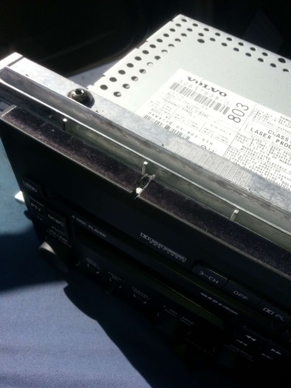 With the headunit back in place and the OLED display awaiting attachment to the dash we fitted a Brodit/ Pro-Clip V70 phase one centre airvent clip to straddle the cup holder which is nearly a perfect fit, to this a Brodit Samsung S3 powered phone holder was secured with the cable running through to the glovebox:  The Brodit phone holder was plugged in to the glovebox mounted charger outlet adapter as was the USB power feeder cable going to the Road Angel camera detector, this leaves two spare sockets for further expansion: 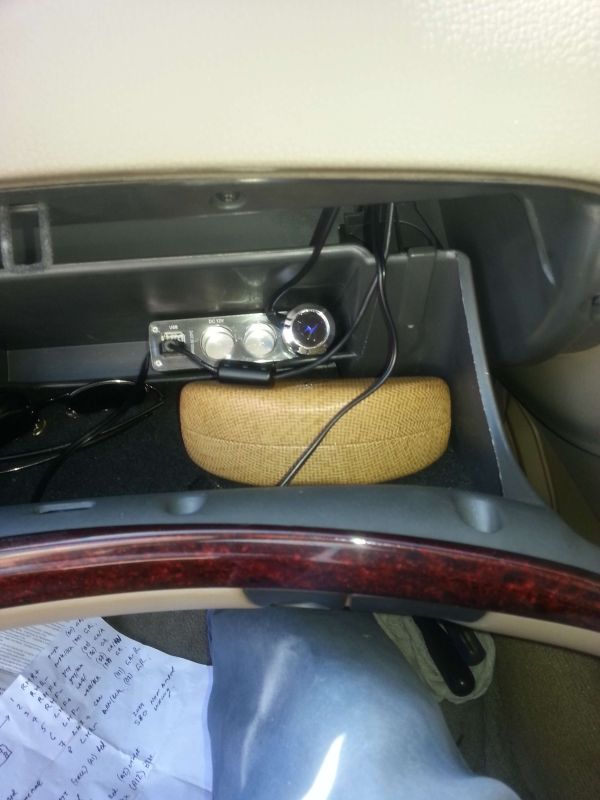 OLED Display in position as is the small volume/ track selector unit on the lower switch panel which just needs a touch up with black indelible ink to hide the small incision made for the cable to run through the plastic: 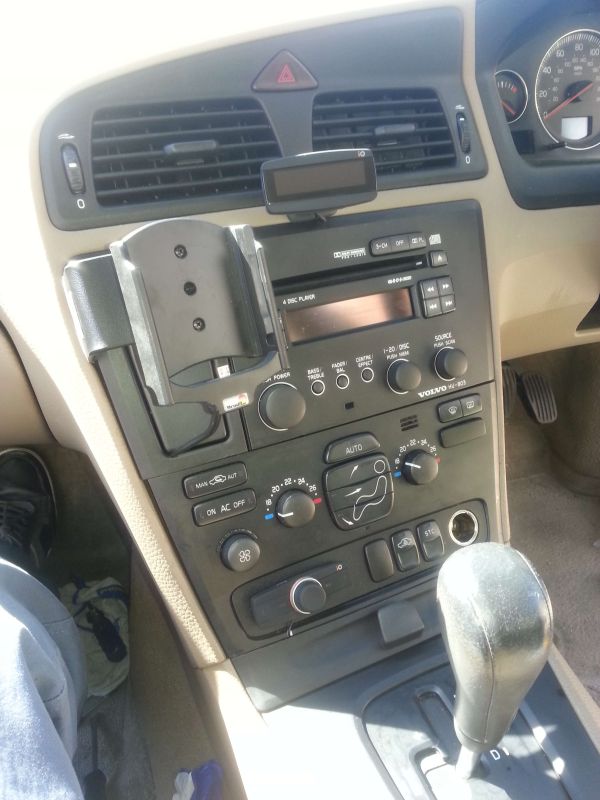 Some five hours after starting this job with the car back together, the ignition key was put to position 2 and the battery negative wire reconnected, with the SmartPhone in its holder decent music (depends upon your taste if you can read the out of focus picture) is streaming from the car speakers via Bluetooth or any of the other available inputs, get bored and you can revert back to the stock Volvo system at the click of a button: 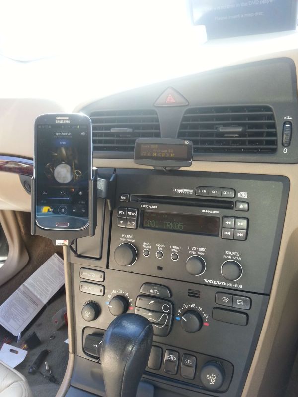 If anyone wants a wiring diagram of how this little lot is connected I will create one and add it to the thread as a PDF, this could be a very simple way to add handsfree and multiple I/O connectivity to the newer models of car as even those using fibre-optics still need an amplifier to feed the speakers, I guess the only remaining link is where to get such a kit from, I have no connections with this company but have used their products in my own car for some four plus years with no issues, well worth considering if you have read this far see Here - Mike |

|

|
| The Following 6 Users Say Thank You to mikealder For This Useful Post: |
|
Aug 4th, 2013, 00:23
|
#2 |
|
VOC Member

Last Online: Sep 11th, 2019 14:36
Join Date: Aug 2008
Location: Blackpool
|
Thanks for that today mike it really does sound fantastic
|
|
|
|
|
Aug 4th, 2013, 10:18
|
#3 |
|
Where's that 18mm socket?

Last Online: Apr 25th, 2016 23:01
Join Date: Sep 2010
Location: Normally in the dog house, Chester-Le-Street
|
Hmmmm..so the practice on getting my radio out came in handy?
 Still over the moon with my install. Thanks Mike. Still over the moon with my install. Thanks Mike.
|
|
|
|
|
Aug 4th, 2013, 10:32
|
#4 |
|
Premier Member
Last Online: Jan 15th, 2022 11:23
Join Date: Feb 2009
Location: Salisbury (ish)
|
Excellent write up. Think I might have to get myself one now
|
|
|
|
|
Aug 4th, 2013, 10:21
|
#5 |
|
Master Member
Last Online: Jul 4th, 2022 14:37
Join Date: Dec 2004
Location: Kingston upon Thames
|
Wow! You were really serious about this weren't you. I can't believe the amount of work you went to. I really like where you've located the power adapter in the glovebox. Wish I'd thought of that when I attached mine under the centre console. Need to do the same for my S60 (having done the V70) so I'll put it in the glovebox.
Out of interest, where have you located your speed camera detector. Thinking of one myself but not sure where it would look best. Thanks Richard |
|
|
|
|
Aug 4th, 2013, 10:29
|
#6 | |
|
VOC Member
Last Online: Nov 6th, 2016 10:18
Join Date: May 2009
Location: Blackpool UK
|
Quote:
As for the install it was a big job but not too difficult, having had a go at Andy Northface's S80 a week ago which was wired in the same way but didn't have the Volvo amp involved or a centre speaker so I knew how the trim came to bits. - Probably the most difficult portion of the whole job was removal/ re-installation of the drivers seat, bloody heavy and far from easy to get it out through the door aperture - Mike |
|
|
|
|
| The Following User Says Thank You to mikealder For This Useful Post: |
|
Aug 4th, 2013, 10:30
|
#7 |
|
VOC Member
Last Online: Sep 11th, 2019 14:36
Join Date: Aug 2008
Location: Blackpool
|
the road angel is located at the bottom right of the windscreen as its gprs and no laser detector or rader detecter built in and its in the perfect line of sight for me.
|
|
|
|
|
Aug 4th, 2013, 13:00
|
#8 |
|
Forum Support Team

Last Online: Yesterday 14:10
Join Date: Mar 2006
Location: Deep in Makem territory
|
Copied to articles.
Thanks Mike
__________________
Current 04 S80 D5 SE Auto 03 S80 D5 SE Man Previous Volvos 90 240 GL B230FB Auto 96 940 CD 13 V40 D2 R-design 89 745 GLE 98 V90 3.0 24v 98 945 Celebration Auto 96 965 SE Auto 86 744 GL 81 244 DL |
|
|
|
|
Aug 7th, 2013, 15:08
|
#9 |
|
too long to remember
Last Online: Dec 5th, 2022 17:14
Join Date: Dec 2004
Location: Leigh on sea
|
Great write up
looking to do the same for my v70, i assume the amp is in the same place..... one question, how did you know what speakers cables go to what speakers within the vehicle harness? do you have a amp plug pinout? also where did you connect the power feed to? Ta |
|
|
|
|
Aug 7th, 2013, 16:41
|
#10 | |||
|
VOC Member
Last Online: Nov 6th, 2016 10:18
Join Date: May 2009
Location: Blackpool UK
|
Quote:
Quote:
Quote:
Are you intending to fit an iO_play_2 kit like the one in the original post in this thread or something else? - Mike |
|||
|
|
|
|
| Currently Active Users Viewing This Thread: 1 (0 members and 1 guests) | |
| Thread Tools | |
| Display Modes | |
|
|


 Hybrid Mode
