
|
|||||||
| PV, 120 (Amazon), 1800 General Forum for the Volvo PV, 120 and 1800 cars |
 Information
|
|
Heater core & heater valve - which comes first?Views : 3386 Replies : 11Users Viewing This Thread : |
 |
|
|
Thread Tools | Display Modes |
|
|
 Jan 22nd, 2017, 19:10
|
#1 |
|
Member
Last Online: Jan 23rd, 2024 07:52
Join Date: Nov 2010
Location: Cape Town
|
Does it depend on the car model? Does it matter?
In a related thread: http://www.volvoforums.org.uk/showthread.php?t=262208 Ron posted a diagram which showed that the heater core comes first and then the valve. I and someone else questioned this. In my car (1970, B20) the heater valve comes first. However, my heater hoses are no longer original. Stock, by-the-meter, heater hose has been used. So I couldnt be sure. The drawings in the GCP catalog (both B18 and B20) correspond to Rons arrangement. Doubt set in. Must I change my hoses? Not exactly a 5 minute job. I have since looked at some engine bays for 1970 Amazons on the Amazonpictures website: http://www.volvoamazonpictures.se/Vo...php?start=2361 Working back from the latest chassis number, all of them seemed to have the heater valve first and then the core, like in my car. But none of the pics were very clear ... until I got to chassis 349287 (pic copied hereunder) which leaves no doubt. According to CVIs parts list the heater hoses for the B18 and B20 do differ - for the B18 there seems to be only one shaped hose whereas, for the B20, all three the hoses are shaped. So, was the order changed when Volvo changed from B18 to the B20? |

|

|
|
Jan 23rd, 2017, 01:56
|
#2 |
|
Premier Member

Last Online: Today 01:20
Join Date: Jul 2007
Location: Connecticut, USA
|
Simon;
This is a scan from the factory manual, with my mark-ups:  I hope it helps. Cheers |
|
|
|
| The Following 2 Users Say Thank You to Ron Kwas For This Useful Post: |
|
Jan 23rd, 2017, 12:44
|
#3 |
|
VOC Member

Last Online: Yesterday 20:59
Join Date: Jul 2006
Location: Chatham
|
To add to that, the blue hose goes to the long pipe that that runs along the block underneath the exhaust manifold. The red hose goes to the brass angle connector in the back of the head. This pic is a bit more complete.
NB The picture of the matrix is wrong. Both of the pipes should come out of the front so they go through the holes n the casing. The one for the lower connection shouldn't be at the back. Bad error there on the illustrator's part. Pic came from here http://www.historic-cars.net/histori...1384-4-Heating 
|
|
|
|
| The Following User Says Thank You to Derek UK For This Useful Post: |
|
Jan 23rd, 2017, 14:44
|
#4 |
|
Premier Member
Last Online: Today 01:20
Join Date: Jul 2007
Location: Connecticut, USA
|
Simon; I don't believe routing shown in that picture is correct...it is certainly not consistent with any actual routing I've seen, or the routing shown in the two graphics here. But to answer the question "Does it matter?"...as I've previously noted, it is a series circuit, so from the point of flow, it does not, and as you've previously also pointed out, the only major difference is that if Heater Core comes first in flowpath, Heater Control Valve would be subjected to the cooled Coolant, possibly being a bit gentler on that component (...but I doubt this really matters, it's certainly not critical, since HVC does come first in other models and vehicles). I guess what I'm saying is, I would change hoses at your next convenience to be consistent with documentation shown (not pull over in a panic-stop and feel you must do it before driving another foot)...it's just not that critical!
If using the preformed OE hoses to make these connections, they do have a preferred placement. Derek; Error notwithstanding, that graphic is even better!...I have made corrections and added flow info details! Here you go: 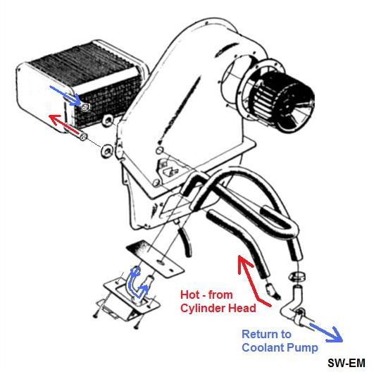 Can you find and post Link to a similar graphic for the 1800, so that I can make a similar flow graphic for that model. Tnx. Cheers Last edited by Ron Kwas; Jan 23rd, 2017 at 17:38. |
|
|
|
| The Following User Says Thank You to Ron Kwas For This Useful Post: |
|
Jan 23rd, 2017, 23:23
|
#5 |
|
VOC Member
Last Online: Yesterday 20:59
Join Date: Jul 2006
Location: Chatham
|
Ron, click the link in my post. The page also shows the partial routing for an ES. Interestingly the 1800 does have a pipe out of the back of the matrix which comes out behind the fan housing. The short right angle hose for that goes to the lower tube on the heater valve. The long hose that goes back to the outside pipe that goes back to the pump goes on the top fitting on the valve. Valve is different on the 1800 and has the in/out coming out of the side of a vertical tube. If you don't have an 1800 parts book I will do a screen grab from the one I have downloaded onto my PC.
|
|
|
|
| The Following User Says Thank You to Derek UK For This Useful Post: |
|
Jan 24th, 2017, 00:26
|
#6 |
|
Premier Member
Last Online: Today 01:20
Join Date: Jul 2007
Location: Connecticut, USA
|
Derek;
In studying that linked site, I have figured out what was wrong with that Graphic...they (wrongly) combined the 122 HCV with HC on an 1800. On the 1800, the HC does indeed exit toward the rear, but the HVC is slightly different again from the 122HCV. I'll see about making a combined graphic which shows both and clears this up. Cheers Edit: I just saw your post...looks like we both figured it out! |
|
|
|
| The Following User Says Thank You to Ron Kwas For This Useful Post: |
|
Jan 24th, 2017, 10:28
|
#7 |
|
Premier Member
Last Online: Today 01:20
Join Date: Jul 2007
Location: Connecticut, USA
|
Forum;
Improved Coolant Flow graphic showing 122 and 1800 variations (HCV is on cold side of HC in both cases): 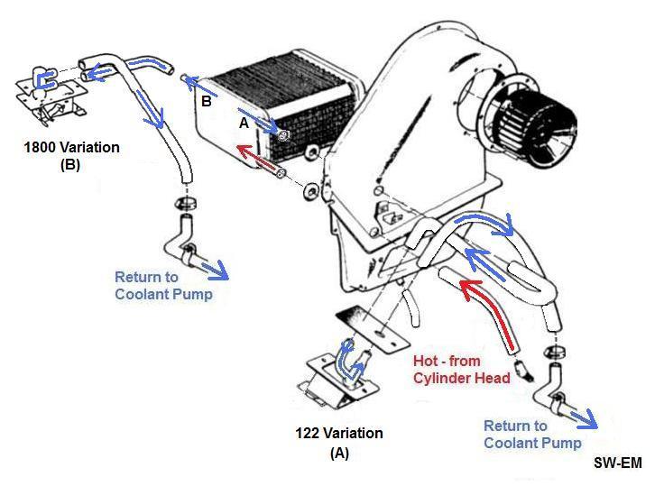 Cheers |
|
|
|
|
| Currently Active Users Viewing This Thread: 1 (0 members and 1 guests) | |
|
|


 Hybrid Mode
