
|
|||||||
| 850 / S70 & V70 '96-'99 / C70 '97-'05 General Forum for the 850 and P80-platform 70-series models |
 Information
|
|
Crankcase breather schematic non-turboViews : 7053 Replies : 10Users Viewing This Thread : |
 |
|
|
Thread Tools | Display Modes |
 Aug 5th, 2009, 18:18
|
#1 |
|
New Member
Last Online: Jul 8th, 2011 10:42
Join Date: Aug 2009
Location: Beaconsfield
|
I have the task of changing my daughter's 850 estate crankcase breather system and I have found the excellent step-by-step guide to the job for the turbo model, but this one is n/a and the pipework is different. Two pipes have become disconnected and it would be wonderful if anyone has a diagram of the non-turbo PCV pipework layout please.

|

|

|
|
Aug 5th, 2009, 18:46
|
#2 |
|
Member

Last Online: Feb 14th, 2015 20:34
Join Date: Feb 2009
Location: Yorkshire
|
Think it might be same as a 1997 S70 non-turbo?? Correct oil trap for mine was the 850 item.
Some models seem to have 2 pipes coming out of the top whereas mine only had one. I've read before that if it has 2 pipes coming out of top then they need fitting a certain way, also read that it doesn't matter on n/a models, unsure which is correct. Few photos I did take might help you.      
|
|
|
|
|
Aug 5th, 2009, 20:34
|
#3 | |
|
Pure is Beautiful

Last Online: Apr 13th, 2021 19:44
Join Date: Nov 2003
Location: UK/
|
Hi,
From you pictures below, I take it the inlet manifold has to come off as the oil trap is buried beneath? Cheers, T Quote:
__________________
I Think. I Think I Am; Therefore I Am - I Think . . . . |
|
|
|
|
|
Aug 5th, 2009, 21:09
|
#4 |
|
Member
Last Online: Feb 14th, 2015 20:34
Join Date: Feb 2009
Location: Yorkshire
|
Hi yes its well buried under the inlet manifold.
You might only need to loosen the lower manifold bolts if its slotted to lift off. On mine theres a couple of hidden bolts fixed under the manifold, one on oil dipstick tube and one on a support brace which is totally hidden. 12mm heads I think. |
|
|
|
|
Aug 5th, 2009, 21:46
|
#5 | |
|
Pure is Beautiful
Last Online: Apr 13th, 2021 19:44
Join Date: Nov 2003
Location: UK/
|
Quote:
Frankly it sounds like a SOAB, and what with the ongoing problems that have arisen with our 'mint' 2.5 20v, I think I'm close to sending it to the local auctions and starting over! Cheers, T
__________________
I Think. I Think I Am; Therefore I Am - I Think . . . . |
|
|
|
|
|
Aug 6th, 2009, 00:43
|
#6 |
|
Member
Last Online: Feb 14th, 2015 20:34
Join Date: Feb 2009
Location: Yorkshire
|
Mines a 10v but think it will be pretty much same as yours.
Its not that hard of a job really, more fiddly than anything especially the manifold bolts. I only needed to buy new oil trap (£14 from volvo) and manifold gasket (£11) because after cleaning out the pipework it was all ok and unsplit etc. I was going to remove the flame trap (like volvo suggest) seen as it causes problems but someone has already removed it. One thing I try to remember is that the engine block is alloy and very easy to strip threads. I've gotten used to working on cast iron engines up til now. |
|
|
|
|
Aug 6th, 2009, 08:36
|
#7 |
|
New Member
Last Online: Jul 8th, 2011 10:42
Join Date: Aug 2009
Location: Beaconsfield
|
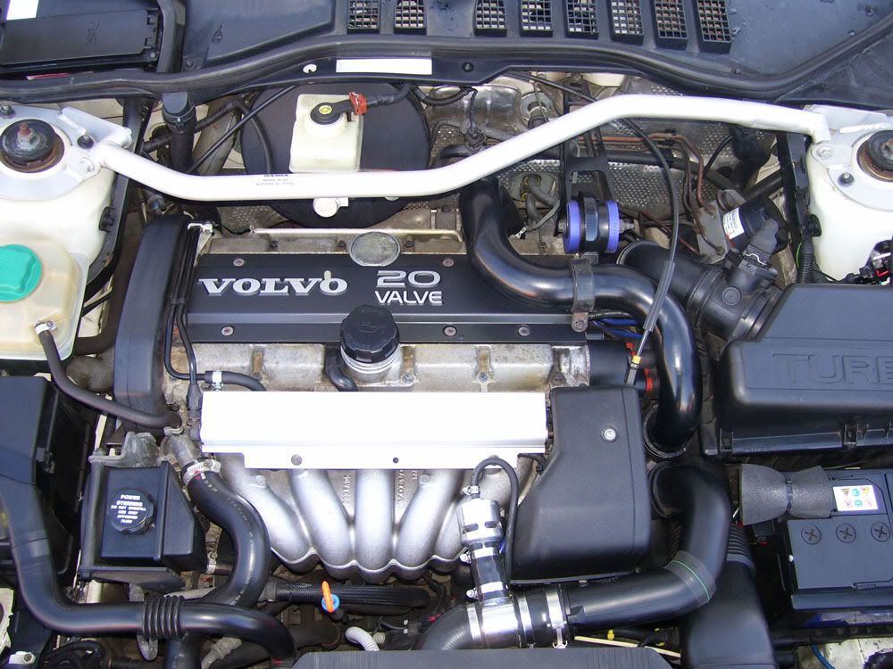
JonYorks, Many thanks for the pictures. It is a bit different as the picture below will show - if I succeed in uploading it that is. The pic is not mine/my daughter's and it is a turbo but the pipe hard against the oil filler is a duplex pipe and one is a hard small diameter pipe like a vacuum tube. It goes somewhere, clearly, but it's come off and I am not sure where it goes. Theres another like it under the manifold and I think that comes from the black plastic device in your first picture - the one with three spigots on one side and two on the other. The upper spigot on the two spigot side has a broken stub of rubber on that seems to accord with the broken stub on the end of the loose pipe from under the manifold - not the duplex pipe from the cam chamber, but the other unknown pipe. You see my difficulty...
|
|
|
|
|
Aug 6th, 2009, 11:52
|
#8 |
|
Member
Last Online: Feb 14th, 2015 20:34
Join Date: Feb 2009
Location: Yorkshire
|
Is the small diameter pipe connected at the left side of inlet manifold? (Can see it loose in my 4th photo)
If I remember correctly then the pipe coming from the top spigot you mentioned goes to there. Its quite hidden but if you can look down the side of the manifold near the pipe that comes from the header tank you should see the pipe. Last edited by JonYorks; Aug 6th, 2009 at 11:56. |
|
|
|
|
Aug 6th, 2009, 13:01
|
#9 |
|
New Member
Last Online: Jul 8th, 2011 10:42
Join Date: Aug 2009
Location: Beaconsfield
|
That looks about right Jon, it is long enough to reach without straining, but the other loose one would be too tight so I suspect you're right. A member on another forum I subscribe to (Westfield Sports Car Club) has come up with a diagram from the VADIS DVD and that should confirm what you say. I must say that this forum, and WSCC, are both very helpful. Some others I read or contribute to are far less helpful - thanks again for your assistance.
|
|
|
|
|
Aug 7th, 2009, 13:57
|
#10 |
|
Member
Last Online: Feb 14th, 2015 20:34
Join Date: Feb 2009
Location: Yorkshire
|
Just looked today and I remembered wrong, the top pipe on the multi spigot thing (in my first photo) actually goes to the fuel pressure regulator.
So the small pipe which comes from the end of the inlet manifold goes across to the flame trap which is the same place the pipe from the top of the oil trap goes to. |
|
|
|
|
| Currently Active Users Viewing This Thread: 1 (0 members and 1 guests) | |
|
|


 Linear Mode

