
|
|||||||
| PV, 120 (Amazon), 1800 General Forum for the Volvo PV, 120 and 1800 cars |
 Information
|
|
PV coil armored cable conversionViews : 1185 Replies : 13Users Viewing This Thread : |
 |
|
|
Thread Tools | Display Modes |
 Apr 4th, 2018, 10:48
|
#1 |
|
arcturus

Last Online: Yesterday 07:31
Join Date: Mar 2006
Location: Sagres Portugal
|
Hi, opened up spare coil and switch as I would like to have access to the + side of coil. First of all, looking at the photo, you can see a wire coming from the large connection clip soldered to the center. will the clip be the connection or only the center pin? Secondly re' the switch. The cable disappears inside the switch. would a connection to terminal 54 service the coil or will there be another connector inside?
__________________
life's too short to drink bad wine 
|

|

|
|
Apr 4th, 2018, 13:04
|
#2 |
|
Premier Member

Last Online: Today 01:20
Join Date: Jul 2007
Location: Connecticut, USA
|
Arcturus;
I'm not certain I understand fully you questions, but I'll try to elaborate on what I believe you're asking... 1. " will the clip be the connection or only the center pin" ...anywhere along that wire, including terminal at the Ign Coil, is the Ign Pos node which you have attained access to...anything you'd like to connect to this node can be connected at any point along that conductor... 2. "would a connection to terminal 54 service the coil or will there be another connector inside? " ...the movable contact within Switch connects Term 30 to both term 54, and a "buried" contact that this wire is connected to when in Pos 3. There are no further connectors inside Ign Sw. Reference my not physically, but electically correct representation of what goes on within the Ign Sw: 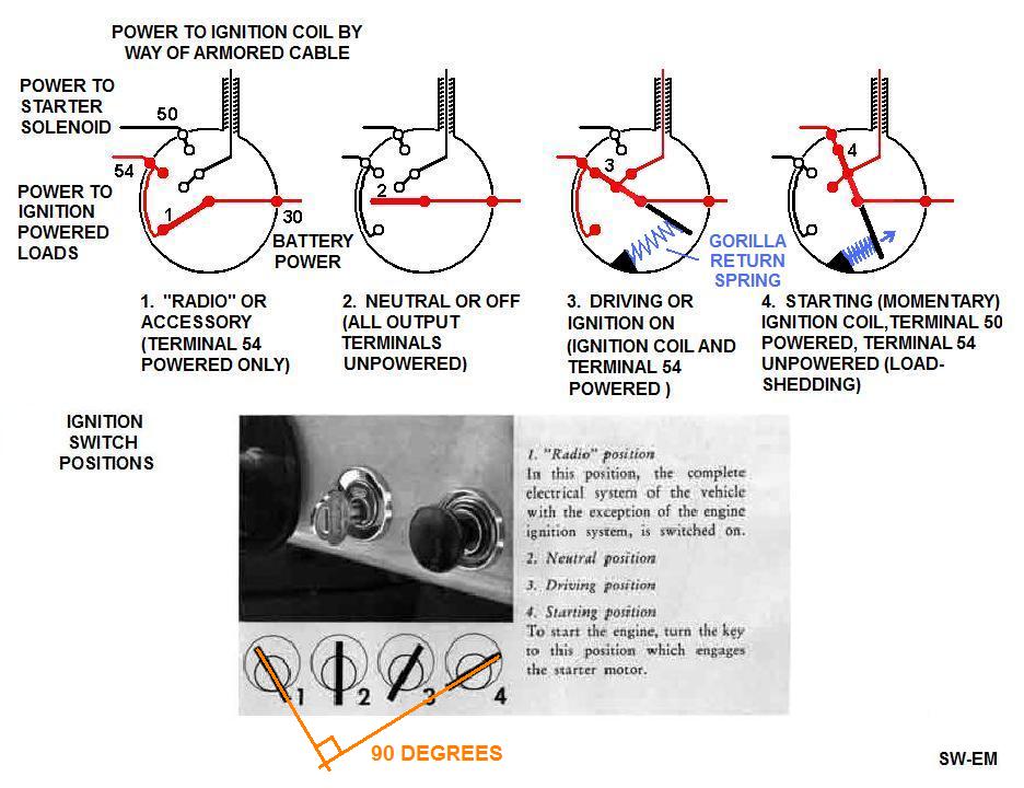 ...see also a dismantling of a Switch if you want to see actual internals: https://www.youtube.com/watch?v=hfuUbguT9Gw hope that helps! Edit: BTW...that is the cleanest access to this wire I've ever seen...clean cutting, and a clean picture of both ends (request permission to repost pic with attribution!)...I'm not sure why you felt you needed to cut it open to gain access, but you certainly have it now...but you have lost the first line of defense against theft in that you have removed the inability to "Hot-Wire". I hope you had a good reason for this...unless it was a trash assembly and you just had to satisfy your curiosity...?! Last edited by Ron Kwas; Apr 4th, 2018 at 13:12. |
|
|
|
| The Following User Says Thank You to Ron Kwas For This Useful Post: |
|
Apr 4th, 2018, 13:58
|
#3 |
|
arcturus
Last Online: Yesterday 07:31
Join Date: Mar 2006
Location: Sagres Portugal
|
No problem, no attribution necessary. Unfortunately the video didn't show where the +wire was attached inside the switch. The wire is quite brittle but I think that I will cut it shorter and solder a connector onto it. A piggy back connector on the coil. I am doing this so that should I decide to fit a 123 dizy i have access to the + terminal or alternatively a tacho'
__________________
life's too short to drink bad wine
|
|
|
|
| The Following User Says Thank You to arcturus For This Useful Post: |
|
Apr 4th, 2018, 14:07
|
#4 |
|
Premier Member
Last Online: Today 01:20
Join Date: Jul 2007
Location: Connecticut, USA
|
arcturus;
"I am doing this so that should I decide to fit a 123 dizy i have access to the + terminal or alternatively a tacho' " ...power an elec dist and tach from term 54 (Reference: http://www.sw-em.com/123Ignition_in_...ored_Cable.htm ) ...and tach doesn't/can't get the RPM signal there, because there is none... ...I hope this work is not unnecessary... Cheers PS. Tnx for use of pic! |
|
|
|
| The Following User Says Thank You to Ron Kwas For This Useful Post: |
|
Apr 4th, 2018, 14:33
|
#5 | |
|
arcturus
Last Online: Yesterday 07:31
Join Date: Mar 2006
Location: Sagres Portugal
|
Quote:
__________________
life's too short to drink bad wine
Last edited by arcturus; Apr 4th, 2018 at 14:36. |
|
|
|
|
| The Following User Says Thank You to arcturus For This Useful Post: |
|
Apr 4th, 2018, 15:13
|
#6 |
|
Premier Member
Last Online: Today 01:20
Join Date: Jul 2007
Location: Connecticut, USA
|
arcturus;
Term 54 is simply the Ign Power terminal...nothing more, nothing less...just remember that it does not have power in key Pos 4 due to Load-Shedding (see graphic!)...so you must power elec ign with the "diode wire" OR install Start Sw Upgrade which means you no longer use Pos4, so don't have to be concerned with Load-Shedding. Cheers |
|
|
|
| The Following 2 Users Say Thank You to Ron Kwas For This Useful Post: |
|
Apr 4th, 2018, 20:33
|
#7 |
|
Master Member
Last Online: Apr 23rd, 2024 15:48
Join Date: May 2017
Location: New Milford, Connecticut
|
Ron, not to hijack the thread, but if I'm expected to understand these wiring diagrams....
What does the references on the wiring diagram, e.g. "1.5 SVART", "2.5 SVART", "6 SVART", signify? Similarly something like "2.5 GRA", "6 GRA" and 2.5 "GRON"? I assume these latter ones are grounded wires. But does the number signify gauge of the wire? Amperage? Thanks. |
|
|
|
|
Apr 5th, 2018, 01:11
|
#8 |
|
Premier Member
Last Online: Today 01:20
Join Date: Jul 2007
Location: Connecticut, USA
|
bs;
Number is wire cross-sectional area in (square)cms, colors follows in Swedish or abbreviation. Cheers |
|
|
|
| The Following User Says Thank You to Ron Kwas For This Useful Post: |
|
Apr 5th, 2018, 13:25
|
#9 | |
|
arcturus
Last Online: Yesterday 07:31
Join Date: Mar 2006
Location: Sagres Portugal
|
Quote:
__________________
life's too short to drink bad wine
|
|
|
|
|
| The Following User Says Thank You to arcturus For This Useful Post: |
|
Apr 5th, 2018, 15:01
|
#10 |
|
VOC Member 3801
Last Online: Yesterday 21:45
Join Date: Dec 2004
Location: Castle Douglas
|
Hi chaps, I think the reference is for square millimetres, not centimetres !
6 square cm would be quite a heavy cable even for a VOLVO ! Regards, Richard. |
|
|
|
|
| Currently Active Users Viewing This Thread: 1 (0 members and 1 guests) | |
|
|


 Linear Mode

