
|
|||||||
| PV, 120 (Amazon), 1800 General Forum for the Volvo PV, 120 and 1800 cars |
 Information
|
|
Headlamp faultViews : 1684 Replies : 7Users Viewing This Thread : |
 |
|
|
Thread Tools | Display Modes |
 Oct 2nd, 2016, 22:08
|
#1 |
|
Junior Member
Last Online: Mar 5th, 2018 00:55
Join Date: Feb 2012
Location: Dumfries
|
My '68 Amazon has really, really dim dipped beam headlights. Main beam is fine, but the dipped beam is scarily poor. I have triple checked the earths, swapped out the footswitch, main switch and relay, checked and cleaned all connections including the lamp connectors and the plastic mulitplug in the engine bay. I've even changed the headlights, though they work fine when bench tested. All to no avail.
However when poking about with a multimeter tonight I discovered that if I earthed the double red wire on the relay, the dip beam suddenly became much brighter. Question is, why? The relay is wired as per the wiring diagram so I don't think that is the fault. The spare relay I swapped in was untested, and made no difference to the lights. Could it be that I have TWO faulty relays? Any help much appreciated! |

|

|
| The Following User Says Thank You to Airspeed For This Useful Post: |
|
Oct 3rd, 2016, 22:14
|
#2 |
|
Member
Last Online: Jan 23rd, 2024 07:52
Join Date: Nov 2010
Location: Cape Town
|
My guess: Somehow the red, grey, and black wires to your headlamps got transposed.
First diagram: The way it should be. Second diagram: The way I think yours are now. That will explain why, on dipped beam, the light output is so poor - the current has to flow through the dipped beam and main beam filaments in series (instead of just through the dipped beam filament). ...and why the dipped beam improves if you earth the red wires on the flash relay - dont try that when the foot switch is in the other position! |
|
|
|
|
Oct 3rd, 2016, 22:26
|
#3 |
|
Premier Member

Last Online: Today 00:40
Join Date: Jul 2007
Location: Connecticut, USA
|
As;
"...poking about with a multimeter tonight..." ...typically, multimeters are used for making accurate Voltage, Current or Resistance measurements in the course of tracing circuit action, "... I discovered that if I earthed the double red wire on the relay, the dip beam suddenly became much brighter. " ...that sounds scary! I recommend against applying a chassis connection to random nodes, to see what happens, unless you want to greatly increase the scope of your troubleshooting! I suggest you learn proper use of Multimeter, then use it to precisely locate what is likely a voltage drop in the Lo/Dipped Beam circuit...typically an oxidized or loose connection in the current path...when Lo/Dipped Beam is powered, Battery voltage (minus .5V max) should be measured at the Headlight elements. Do not "poke about" and connect random points to chassis (I urgently recommend you don't try that while Hi/Main Beam is energized!). Good Hunting! |
|
|
|
|
Oct 4th, 2016, 00:02
|
#4 |
|
Junior Member
Last Online: Mar 5th, 2018 00:55
Join Date: Feb 2012
Location: Dumfries
|
Simon, I see what you mean. Sitting here, I'm certain that hasn't happened, but the reality might be completely different! I'll check - thanks.
Ron, when 'poking about' I was actually checking for a voltage drop at each and every connection - as they were all cleaned and remade already, there wasn't one, as I knew there wouldn't be when I started. That checked, and the lamps and switches all checked, there isn't much left in the circuit! I was surprised to find a current passing through all three terminals on the relay though - I always thought they work as a switch, and that one pole would show a zero voltage when on dip (and the other when on main beam). However Simon's diagram makes sense and would explain that, so I'll have a look tomorrow. Give me a rotten sill any day... |
|
|
|
|
Oct 4th, 2016, 08:48
|
#5 |
|
Premier Member
Last Online: Today 00:40
Join Date: Jul 2007
Location: Connecticut, USA
|
As;
If no wiring has been changed, we must use Simon's drawing number 1. And if applying a chassis connection to the Red (Hi/Main Beam) wire caused the Lo/Dipped Beam to become brighter, then it means that adding that conductor (Blue) improved the chassis current path, even though it was still through the Hi/Main Beam Element, as shown in my markup of Simon's drawing here: 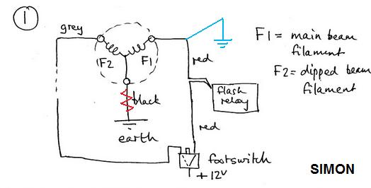 ...which in-turn still suggests to me a poor chassis connection at Red. I suggest you measure and report voltages at Headlight Element. Good Hunting! |
|
|
|
|
Oct 4th, 2016, 19:16
|
#6 | |
|
Member
Last Online: Jan 23rd, 2024 07:52
Join Date: Nov 2010
Location: Cape Town
|
Quote:
To help you with your fault tracing, here is my earlier diagram, with the rest of the wiring of the flash relay included. Yes, there should always be 12 volts on the black wire of the flash relay. Also on the grey wire. (No current through the relay coil = no voltage drop across the relay coil, which means: voltage on grey wire = that on the black wire.) It is only when the stalk switch is operated that the voltage on the grey wire drops to zero (and current starts flowing through the relay coil to give a full 12 volt drop across the coil). If you measure a voltage on the double red wire when the foot switch is in the dipped beam position, you have a problem somewhere. The red wire should have a voltage on it only when (a) the light switch is on and the foot switch is in the main beam position, or (b) the stalk switch is operated (whether the light switch is on or off). |
|
|
|
|
| The Following User Says Thank You to simonvolvo For This Useful Post: |
|
Oct 4th, 2016, 19:43
|
#7 |
|
Premier Member
Last Online: Today 00:40
Join Date: Jul 2007
Location: Connecticut, USA
|
...good info from Simon!
Simon; If as I suspect, there is a resistance between chassis and Headlight Element return pin, a voltage drop would develop due to Lo/Dipped Beam current flowing, and that would be measurable with multimeter at the Red wire. As; What is magnitude of voltage you are measuring on Red wire? Cheers |
|
|
|
|
Oct 6th, 2016, 16:56
|
#8 |
|
Member
Last Online: Jan 23rd, 2024 07:52
Join Date: Nov 2010
Location: Cape Town
|
@Airspeed:
If you do indeed have a bad earth (I thought you had triple checked them???) I would suggest you test each side with the light bulb on the other side having been removed from its socket. That makes things much, much simpler. In other words, remove the left hand bulb, switch on the lights, and operate the foot switch between dipped beam and main beam and observe if that side works as it should. Re-insert the left hand bulb and remove the right hand bulb, and repeat the test. This will immediately tell you on which side the problem lies. All sorts of complications arise if both light bulbs are connected, because the lamp with the bad earth borrows the earth of the lamp with the good earth. Refer to the diagrams below. They show the way the currents flow for (1) dipped beam and (2) main beam (when one of the earth connections is broken). You will see that various filaments that shouldnt have a current going through them do have a current going through them. The green current is only about a third as high as the blue current because it has to go through three filaments in series instead of through just one. |
|
|
|
| The Following User Says Thank You to simonvolvo For This Useful Post: |
|
| Currently Active Users Viewing This Thread: 1 (0 members and 1 guests) | |
|
|


 Linear Mode

